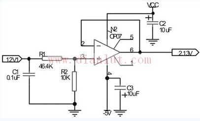
The signal conditioning circuit mainly performs filtering, voltage division and impedance matching on the input power detection signal. The purpose of filtering is to filter out high-frequency glitch in the detection signal. It can be seen through experiments that there is often a large amplitude interference glitch in the antenna power signal. If it is not filtered, it may cause damage to the device or affect the detection accuracy. The purpose of voltage division is to change the amplitude of the detection signal to meet the input requirements of the A/D converter. The key to the design is to ensure that the amplitude of the signal does not exceed the input requirements of A/D, and the signal should be increased as much as possible. Resolution. The impedance matching circuit is an emitter follower, which aims to perform impedance matching before and after, and improve the accuracy of detection. The figure shown is a conditioning circuit for the 12V detection voltage.
Piezoelectric Discs For Flowmeter Sensor
Piezoelectric ceramic disc
Quick delivery
High performance
Application: flow meter measurement
There are many kinds of USF used in closed pipeline according to the measuring principle, and the most commonly used are propagation time method and Doppler method. Among them, time difference ultrasonic flowmeter is used to measure fluid flow by the principle that the time difference of sound wave propagating downstream and countercurrent is proportional to the velocity of fluid flow. It is widely used in raw water measurement of rivers, rivers and reservoirs, process flow detection of petrochemical products, water consumption measurement of production process and other fields. According to practical application, time-difference ultrasonic flowmeter can be divided into portable time-difference ultrasonic flowmeter, fixed time-difference ultrasonic flowmeter and time-difference gas ultrasonic flowmeter.
Ultrasonic flow-meters use at least two transducers aligned so that ultrasonic pulses travel across the flow of liquid or gas in a pipe at a known angle to the flow.
Technical data:
Electromechanical coupling coefficient Kp: > 0.62
Dielectric Loss tg δ: <2%
Nominal Piezo discs for ultrasonic flowmeter:
OD14.2*1MHz PZT-51
OD14.6*1MHz PZT-51
OD15*1MHz PSnN-5
OD15*2MHz PSnN-5
OD20*1MHz PSnN-5OD20*2MHz PSnN-5
OD15*1MHz PZT-51
OD15*2MHz PZT-51
OD20*1MHz PZT-51OD20*2MHz PZT-51
Size, Frequency and Electrode on request.


Piezoelectric Ceramic Disc,Piezoelectric Disk Flow Meter,Piezoelectric Flow Sensor,Piezo Discs Flowmeter
Zibo Yuhai Electronic Ceramic Co., Ltd. , https://www.yhpiezo.com