In many MCU applications, the serial port is connected to the serial port of the computer for data transmission or control command transmission and reception. A large part of the serial port of the MCU is to use the level standard (PIC can be directly connected to the serial port of the computer), its logic 1 level is 5V, the logic 0 level is 0V, and the computer serial port is used. The level standard, its logic 1 level is -3V--12V, and the logic 0 level is +3V-+12V. The level ranges of the two are very different, so the circuit is needed for connection. There are many kinds of circuits in this way. Generally, the commercialized finished products will use dedicated RS232 and TTL level-shifting integrated circuits such as MAX232 and DS275. For ordinary electronic enthusiasts, the use of such devices is not very good. To increase the cost of production, what kind of circuit is used to replace them? The following is a combination of experience in practical design applications to introduce these circuit materials, but also introduce some of the experience of circuit design applications.
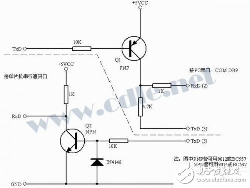
Figure 1 shows a level-shifting circuit built using a low-power triode. One tube and tube are used respectively. The NPN can use the commonly used 9014 or BC547, and the PNP can use the commonly used 9012 or BC557. The circuit is divided into two parts, transmission and reception, which have been separated by a dotted line in Figure 1. They can be used separately or together. The transmission circuit uses a PNP tube. When the TxD signal of the MCU is logic high, Q1 is turned off, and the TxD (3) of RS232C provides about -9V (actually different according to the serial interface chip used on the computer motherboard) to RS232C RxD (PIN2). When the TxD signal of the MCU becomes a logic low level, Q1 is turned on, and about +5V is transmitted to RxD (PIN2) of RS232C. When transmitting data in this way, the RS232C's TxD (PIN3) must be stable at around -9V.
A receiving circuit below the dotted line that converts the RS232C level to a TTL logic level. When the PC sends data to the TxD (PIN3) of the RS232C, the logic 1 level is -9V, and Q2 is turned off. At this time, the RxD of the microcontroller is about +5V. When RS232C's TxD is logic low level is +9V, Q2 is turned on, and the microcontroller RxD is about 0V at this time.
It is also often used in the circuit of Figure 1 to replace the MAX232, DS275 chip, which can not only use the transmission or receiving part alone, but also works well in some projects that require two-way transmission. I usually use the 9600 baud rate, but I can actually work at a higher baud rate. It can also be soldered to a small 8-pin IC socket or PCB directly to replace the DS275 (see Figure 2 for the DS275 pin function description).
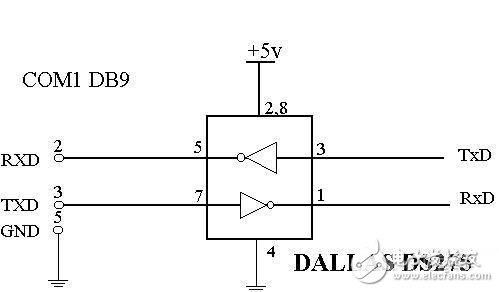
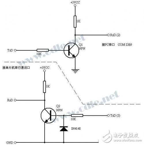
Figure 3 is another RS232/TTL level shifting circuit. For the receiving circuit, it is the same as the circuit of Figure 1. The circuit uses 2 NPN low power, the transfer circuit does not need to refer to the negative voltage from the TxD of RS232C, and if so, when the TxD of the single chip is high level, the RxD of the RS232C is 0V (not as shown in Figure -9V). When it is low, the RxD of RS232C is +5V. Obviously this is different from the standard of RS232C, but most PC serial ports can accept such a range of levels. This circuit can be used to replace the DS275 chip directly as shown in Figure 1.
The transistors in these two circuits can be replaced by most of the commonly used small power transistors. I use 9012, 9014, BC547, BC557 myself, and they all work well. It should be noted that the level range they produce is not the standard RS232 level, so the nominal transmission distance of RS232 cannot be achieved.
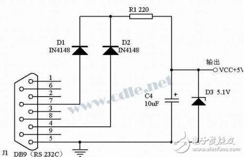
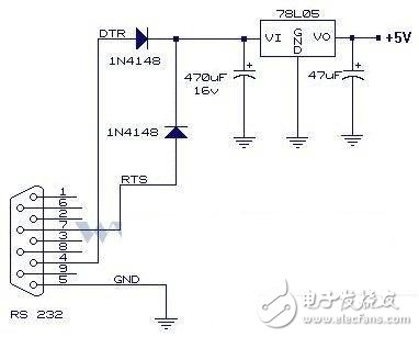
In some small applications, a single 2051 or PIC chip and a few small components are usually used, and their power consumption is very small. Generally, a few dozen milliamps is enough. In my own PC project, I used an AT89C2051, an integrated infrared receiver and a small, small resistance container and the transmission part of the circuit mentioned above. The total power consumption is only ten milliamps. I use the circuit of Figure 4 to steal electricity directly from the PC serial port, the effect is very good, can provide 5V, more than 20 mA. The circuit of Figure 5 can also be used. However, it should be noted that both circuits require the upper software to make the 7 and 4 pins of the serial port high to be able to take power normally, otherwise the required voltage cannot be stolen from the serial port.
recordable stuffed toy:
Ningbo AST Industry Co.,Ltd has 17 Years Experiences to produce the Recordable Plush Toy,Stuffed toy,Teddy Bear,Soft Toys ,Musical Plush toys and so on ,we can assure you of competive price,high quality,prompt delivery and technology supporting.
1. recordable stuffed toy application :
The Recordable Plush Toys as the Gifts can record your own and present them to your friends,children and family.
2.Press the Record Button to record your Own Message,then press the play button to play the message.
3.Recording time:12s,20s,30s and so on
4.Sound Quality:Clearly and Loudly
5.Packaging;Color box
6.Certification:CE ,Rohs
7.Export to:
USA, UK,Canada,Germany, Turkey,Russia,Poland,Switzerland,Netherland ,Frence Hungary ,Australia,New Zealand, Brazil, Columbia,Argentina,Thainland,Singapore , Malaysia and so on
  |
|
Recordable Plush Toy, Musical Teddy Bear, Recordable Stuffed Toy
AST Industry Co.,LTD , https://www.astsoundchip.com