The A/D conversion is to convert the analog quantity V (such as V=5V) into the digital quantity D (such as D=255). There are many types of analog/digital (A/D) conversion, such as counting comparison type, successive approximation type, double integral type, and the like. The successive approximation type is commonly used in integrated circuit devices, and the basic working principle of successive approximation A/D is briefly introduced.
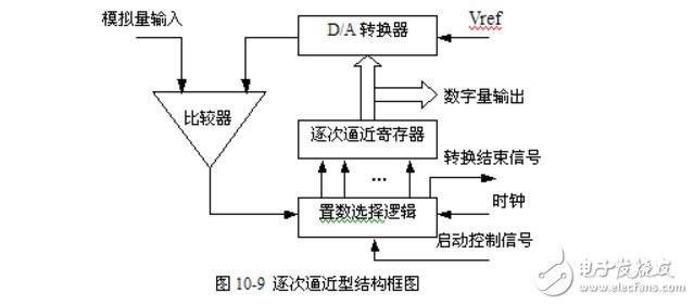
The figure shows the structure of the successive approximation. This A/D converter is based on a D/A converter, plus a comparator, a successive approximation register, a set selection logic, and a clock. The conversion principle is as follows.
Under the control of the start signal, the first selection logic circuit is set to give the highest position of the successive approximation register "1". After D/A is converted into an analog quantity, it is compared with the input analog quantity, and the voltage comparator gives the comparison result. If the input amount is greater than or equal to the amount output after D/A conversion, the comparator is 1, otherwise 0, the set selection logic circuit modifies the content in the successive approximation register according to the result of the comparator output, so that it passes through D The analog quantity after /A transformation successively approximates the input analog quantity. The digital quantity after several modifications is the amount of A/D conversion result.
Most of the current approximation A/D adopts the binary search method, that is, the 1/2 value of the maximum allowable voltage range is first compared with the input voltage value, that is, the highest is "1" first, and the remaining bits are "0". If the search value is within this range, then the 1/2 value of the range is taken, that is, the second highest position is "1". If the search value is not within this range, then the other 1/2 range of the maximum allowable input voltage value of the search value, that is, the highest bit is "0", sequentially, and the comparison narrows the search range by 1/2 each time. The n-bit A/D conversion can be obtained by n comparisons. The successive approximation method has a faster conversion speed, so the integrated A/D chip mostly adopts the above method.
As can be seen from the figure, the A/D conversion requires an external start control signal to be performed, and is divided into two types: pulse start and level start. The chips that use pulse start include ADC0804, ADC0809, and ADC1210. The chips that use level-on are ADC570, ADC571, ADC572, and so on. This start signal is provided by the CPU. When the A/D converter is started, after n comparisons by the binary search method, the content of the successive approximation register is the converted digital quantity. Therefore, the digital quantity must be taken out of the successive approximation register after the A/D conversion is completed. For this purpose, the D/A chip specially sets the conversion end signal pin, sends a conversion end signal to the CPU, notifies the CPU to read the converted digital quantity, and the CPU can detect the A/D conversion end signal by interrupt or query mode, and from A. The digital register is taken from the data register of the /D chip (ie, the successive approximation register in Figure 10-9).
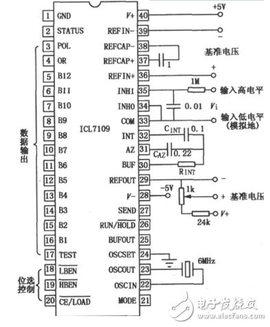
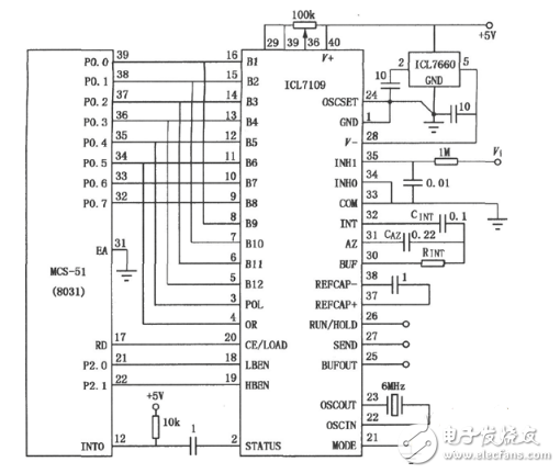
A/D conversion circuit diagram design (1)The interface circuit of ICL7109 is strong, and the output is a 12-bit binary number. Its characteristics are: compatible with TTL circuit; with three-state control output; general signal control terminal, easy to monitor and convert; polarity and overflow bit; on-chip oscillator, UART asynchronous data transmission and reception; serializable, Parallel interface; differential input, differential reference voltage for lower noise and smaller error; with anti-static protection; similar models are TSC7109, ADC7109. Analog part wiring diagram:
1.ANTENK Card Edge Connectors are precision engineered PCB mount connectors developed to mate with the plated fingers of a printed circuit daughter board. Their bifurcated, cantilever contacts are set in a dual readout configuration and they offer a reliable connection for a wide range of PCB thicknesses. ANTENK`s sturdy solder tails with tapers allow easy insertion and rugged durability
Card Slot Connectors Specification:
*Electrical Characteristitics:
Current Rating;0.5A.
Withstanding Voltage:AC500V r.m.s.
Insulation Resistance:1000Megohms Minimum at DC 500V
Contact Resistance:100Miliohms Maximum.
*Mechanical Characteristics:
Mating Cyeles:5000 Insertions.
*Environmwntal:
Operating Temperture:-40°To+60°
*Material:
1.Housing:HI-Temp plastic UL 94V-0 Rated.
2.Contact:Copper Alloy.
3.Shell:SUS.
*Finish :
1u" Gold plated on conatct area,1u" Gold plated on
solder tails, Base Nickel :50u"Min
*Packing:
Number of connectors:750Pcs/REEL

MATERIAL&FINISH
Insulator:PBT Glass Fiber(UL94V-0)
contact:Brass
Contact:Gold-Plated Over Nickel
SPECIFICATIONS
Current Rating:1A AC,DC
Voltage Rating:250V AC,DC
Temperature Range:-40℃ To+105℃
Contact Resistance:20mΩMin
Insulation Resistance:1000MΩ Min
Withstanding Voltage:500V AC/Min
Video Card Connectors,Card Slot Connectors,Card Edge Slot Connector,CF Card Connector, Edge Card Connector,Memory Card Connector,PC Card Connector,SIM Card Connector,Smart Card Connector
ShenZhen Antenk Electronics Co,Ltd , https://www.antenkelec.com