0 Overview
Lingang GLP will be the largest and highest-standard industrial logistics park in Shanghai, with a total area of ​​about 3.2 square kilometers to be completed in three phases, of which the first phase covers an area of ​​about 110,000 square meters, and the second phase covers an area of ​​about 190,000 square meters. Meters, the third phase covers an area of ​​about 200,000 square meters. The project provides modern logistics and storage facilities for the development of Yangshan Deepwater Port and the construction of Lingang New City. The total investment of the project is nearly 300 million U.S. dollars. Lingang GLP International Logistics Park is located in Shanghai Lingang Industrial Zone, with the Hulu Expressway (A2) to the northeast, which can directly connect the A30 and Donghai Bridge; the northeast is near Lianggang Expressway, which can quickly connect Pudong International Airport and Jiangsu and Zhejiang regions. , The southwest side of the park is adjacent to the railway freight center station, which can connect to various coastal cities. It is close to the C4 ring line and the Dishui Lake scenic area in the east, so the traffic is very smooth.
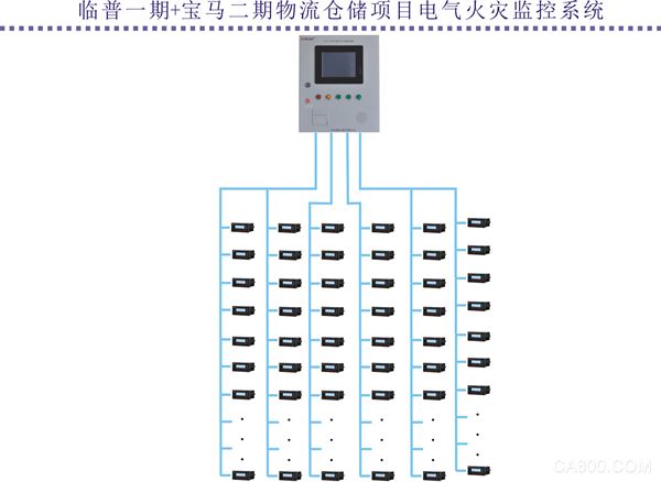
The project undertakes its electrical fire monitoring system. An Acrel-6000/B electrical fire monitoring system host is placed in the fire control room. Through the data collection of 216 ARCM200BL type fire detectors distributed on the floor, the Acrel-6000/ Real-time display and alarm of leakage data of B host.

1 Application introduction
Acrel-6000/B electrical fire monitoring system is a computer monitoring and control system that integrates monitoring, alarm and management independently developed by Ankerui. The system is suitable for large shopping malls, living quarters, industrial and mining enterprises, office buildings, shopping malls, hotels and other areas. Centralized monitoring and management of electrical fire protection.
Acrel-6000/B electrical fire monitoring equipment is the core of Acrel-6000 electrical fire monitoring system. The monitoring equipment is connected to multiple electrical fire monitoring detectors through the RS485 bus to form a distributed electrical fire monitoring system to monitor the work of electrical circuits in real time. state.
The monitoring equipment can receive and process the residual current and temperature signals sent by various detectors in real time, and display them on the LCD screen at the same time. When the residual current, the operating temperature exceeds the limit, and the power supply or communication fails, the monitoring equipment can send out sound and light alarms. Signal, display alarm type, fault location and other information on the screen, with data storage, query, alarm, control output and other functions, and support the remote reset control function of the detector.
This equipment has reasonable structure, small size, high reliability, strong function, convenient maintenance, high cost performance, friendly and intuitive system interface, easy to learn and use.
2 Reference standards
This equipment complies with national standards
GB14287.1-2014 "Electrical Fire Monitoring System Part 1: Electrical Fire Monitoring Equipment"
GB14287.2-2014 "Electrical Fire Monitoring System Part 2: Residual Current Type Electrical Fire Monitoring Detector"
GB14287.3-2014 "Electrical Fire Monitoring System Part 3: Temperature Measuring Electrical Fire Monitoring Detector"
GB50016-2014 "Code for Fire Protection Design of Buildings"
JGJ 16-2008 "Code for Electrical Design of Civil Buildings"
GB50116-2013 "Code for Design of Automatic Fire Alarm System"
GB50054-2011 "Code for Low-Voltage Power Distribution Design"
GB13955-2005 "Installation and Operation of Residual Current Operated Protection Device"
GB50055-2011 "General Electric Equipment Power Distribution Design Code"
GB50217-2007 "Power Engineering Cable Design Code"
3 System composition
The residual current electrical fire monitoring system adopts a hierarchical distributed structure and is composed of a station control management layer, a network communication layer and a field equipment layer. The electrical fire monitoring detectors are connected to the wall-mounted host through the flame-retardant shielded twisted pair RS485 interface and the MODBUS communication protocol bus type connection.
System network structure
1) Station control management
The station control management layer is the direct window of human-computer interaction for the management personnel of the electrical fire monitoring system, and it is also the uppermost part of the system. It is mainly composed of system software and necessary hardware equipment, such as touch screen, UPS power supply, etc. The monitoring system software calculates, analyzes, and processes all kinds of data and information on site, and reflects on-site operation conditions with graphics, digital display, sound, and indicator lights.
Monitoring host: used for data collection, processing and data forwarding. Provide data interfaces inside or outside the system for system management, maintenance and analysis.
UPS: Ensure the normal power supply of the computer monitoring system, and ensure the normal operation of the station control management layer equipment when the power supply problem occurs in the entire system.
The background monitoring equipment is set in the consumer control center.
2) Network communication layer
Communication medium: The system mainly adopts flame-retardant shielded twisted-pair cable, and realizes real-time communication between field equipment and host computer with RS485 interface and MODBUS communication protocol.
3) Field equipment layer
The field equipment layer is the data acquisition terminal, mainly ARCM200BL residual electrical fire monitoring detector. The ARCM200BL residual current electrical fire monitoring detector is designed for TT and TN systems below 0.4kV. It monitors and manages the residual current, wire temperature, overcurrent, overvoltage and other fire risk parameters of the distribution circuit. So as to prevent the occurrence of electrical fires. The product adopts advanced microcontroller technology, high integration, small size, easy installation, intelligent, digital, and networked. It is an ideal choice for building electrical fire prevention and monitoring, and system insulation aging prediction. The product meets the requirements of the national standard GB14287.1-2014 "Electrical Fire Monitoring System Part 1: Electrical Fire Monitoring Equipment".
The distributed I/O controller connected with the field bus constitutes a data collection terminal, which uploads the collected data to the data center. The measurement probe is responsible for the most basic data collection task, and the monitored data must be complete, accurate and transmitted to the monitoring host in real time. It is convenient for operators to monitor the operating status of on-site equipment, fault alarms, etc., and effectively prevent fire accidents.
4) Project networking
The ARCM200BL type fire detectors distributed on the project site are distributed in the floors, and they are networked on-site by hand in hand.
4 system functions
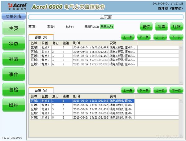
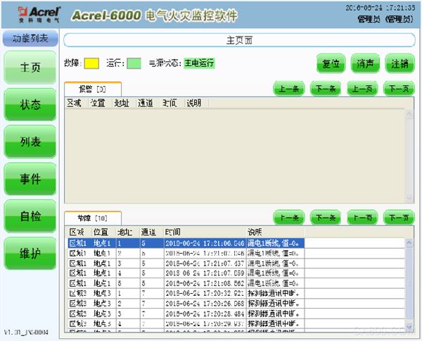
4.1 Monitoring alarm function
The monitoring equipment can receive the residual current and temperature information of multiple detectors, and send out sound and light alarm signals when alarming. At the same time, the red "alarm" indicator on the equipment is on, the display screen indicates the alarm location and alarm type, records the alarm time, and sounds and light alarms. Keep it until you press the "reset" button of the device or the "reset" button of the touch screen to remotely reset the detector. The audible alarm signal can also be manually eliminated by using the touch screen "silencing" button.
4.2 Control output function
When the monitored circuit alarms, the control output relay is closed to control the protected circuit or other equipment. When the alarm is eliminated, the control output relay is released.
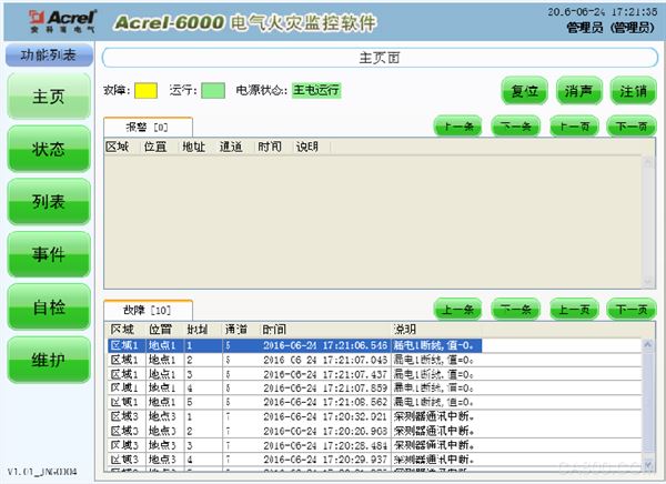
4.3 Fault alarm function
Communication failure alarm: When a communication failure occurs between the monitoring device and any of the connected detectors or the detector itself fails, the corresponding detector in the monitoring screen displays a failure prompt, and the yellow "fault" indicator on the device is on , And issue a fault alarm sound.
Power failure alarm: When the main power supply or backup power supply fails, the monitoring equipment will also send out an audible and visual alarm signal and display the fault information. You can enter the corresponding interface to view the detailed information and cancel the alarm sound.
4.4 Self-check function
Check whether all status indicators, display screens, and speakers in the device are normal.

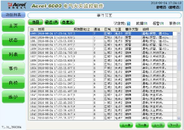
4.5 Alarm record storage and query function
When a residual current, over-temperature alarm or communication or power failure occurs, the alarm location, fault information, alarm time and other information are stored in the database. When the alarm is removed and the fault is eliminated, it is also recorded. Historical data provides a variety of convenient and fast query methods.
4.6 Power supply function
When the main power supply fails, undervoltage and other faults, the monitoring equipment can automatically switch to the standby power supply. When the main power supply returns to normal power supply, it will automatically switch back to the main power supply. The continuous and stable operation of the monitoring equipment is ensured during the switching process.
4.7 Control function of detector
Through the operation of monitoring software, remote reset control of all detectors connected to this equipment can be carried out.
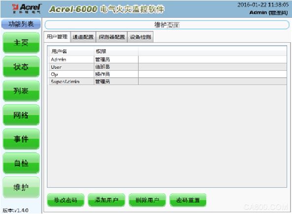
4.8 Access control function
In order to ensure the safe operation of the monitoring system, the operation authority of the monitoring equipment software is divided into three levels, and operators of different levels have different operation authority.
5 Main technical parameters
5.1 Power
â‘ Rated working voltage AC220V (85% ~ 110%).
②Backup power supply: When the main power supply is undervoltage or power failure, the working time of the monitoring equipment is ≥4 hours.
5.2 Work system
24-hour work system.
5.3 Communication method
RS485 bus communication, Modbus-RTU communication protocol, the transmission distance is 1km, and the communication transmission distance can be extended through a repeater.
5.4 Monitoring capacity
â‘ The monitoring equipment can monitor up to 512 monitoring units (detectors);
â‘¡It can be equipped with ARCM series monitoring detectors.
5.5 Monitoring alarm items
â‘ Residual current fault (leakage): the attributes of the faulted unit (location, type);
â‘¡Temperature alarm (over temperature): the attributes of the faulty unit (location, type);
â‘¢Current fault (overcurrent): the attributes of the fault unit (location, type);
④ Monitoring and alarm response time: ≤10s;
⑤ Monitoring and alarm sound pressure level (A weighting): ≥70dB/1m;
â‘¥Monitoring alarm light display: red LED indicator, red light alarm signal should be maintained until manual reset;
⑦Monitor the alarm sound signal: it can be manually eliminated, and when the alarm signal is input again, it can be restarted.
5.6 Fault alarm items
â‘ The communication connection line between the monitoring equipment and the detector is broken or short-circuited;
â‘¡ There is a short-circuit or short-circuit in the connecting wires between the detector and the residual current sensor and the temperature sensor;
â‘¢The main power supply of the monitoring equipment is undervoltage or power failure;
â‘£ The connection line between the charger and the battery for charging the battery is open or short-circuited;
⑤Failure alarm response time: ≤100s;
⑥ Monitoring alarm sound pressure level (A weighting): ≥70dB/1m;
⑦Monitoring alarm light display: yellow LED indicator, yellow light alarm signal should be maintained until the fault is eliminated;
⑧Fault alarm sound signal: it can be manually eliminated, and it can be restarted when there is an alarm signal input again;
⑨ During the failure period, the normal operation of the non-fault circuit will not be affected.
5.7 Control output
Alarm control output: 1 set of normally open passive contacts; capacity: AC250V 3A or DC30V 3A.
5.8 Self-check items
â‘ Indicator inspection: alarm, fault, operation, main power, standby power indicator;
â‘¡Display inspection;
â‘¢ Inspection of audio devices;
④Self-checking time ≤60s
5.9 Event Record
â‘ Record content: record type, occurrence time, detector number, area, fault description, and can store no less than 20,000 records;
â‘¡Record query: query based on conditions such as the date and type of the record.
5.10 Operation authority classification
â‘ Daily duty class: real-time status monitoring, event record query;
â‘¡Monitoring operation level: real-time status monitoring, event record query, remote detector reset, equipment self-check;
â‘¢System management level: real-time status monitoring, event record query, detector remote reset, equipment self-check, monitoring equipment system parameter query,
Each module of the monitoring equipment is individually detected, added and deleted by the operator.
5.11 Use environmental conditions
â‘ Workplace: Fire control room, manned substation (distribution room), on the wall of manned room;
②Working environment temperature: -10℃~50℃;
③Relative humidity of working environment: 5%~95%RH;
④ Altitude: ≤2500m.
6 Equipment components
6.1 Main parameters and components
â‘ Main control unit: industrial-grade tablet computer with touch screen and WinXP operating system;
â‘¡Input and output: built-in intelligent DCMOD module developed by the company, with multiple input and output;
â‘¢Sound and light alarm: built-in horn, LED indicator;
â‘£Backup power supply: 2 maintenance-free batteries of 12V/7.2Ah.
6.2 Panel component layout and function description
The panel layout of Acrel-6000/B electrical fire monitoring equipment is shown in Figure 1:
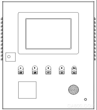
Figure 1 Schematic diagram of monitoring equipment panel
Alarm indicator (red): When the device receives the alarm signal from the detector, the alarm indicator is always on;
Fault indicator (yellow): When the system fails (such as communication failure, power failure, etc.), the fault indicator is always on;
Running indicator light (green): When the device is running normally, the indicator light is always on;
Silence indicator light (green): When the software is silenced, the indicator light is always on;
Reset button (red): reset the system;
Micro printer: used to print real-time alarm, fault, and event information.
Since the system was put into operation, it has been running well and has played an important role in preventing electrical fires, and has won the recognition and trust of customers for the product and the company.
references:
[1]. Fire Bureau of the Ministry of Public Security. China Fire Yearbook. 2014. Yunnan People’s Publishing House. 2014.11
[2]. The National Standard of the People’s Republic of China for the Design of Automatic Fire Alarm System GB 50116-2013. Published by China Planning Publishing House. 2014.3
About the author: You Xiaoyun, female, undergraduate Ankerui Electronic Commerce (Shanghai) Co., Ltd. The main research direction is smart grid power supply and distribution Email:
Mobile QQ
Insulation Acrylic Fiberglass Sleeve
Insulation Acrylic Fiberglass Sleeve,Best Acrylic Coated Fiberglass Sleeving,Acrylic Fiberglass Sleeving,Insulation Acrylic Fiberglass Sleeving
Longkou Libo Insulating Material Co.,Ltd. , https://www.liboinsulation.com