
Points to note:
1. The unidirectional conductivity of the diode, volt-ampere characteristic curve, ideal switch model and constant voltage drop;
2. The process of bridge rectification current flow, input and output waveforms;
3. Calculation: Vo, Io, diode reverse voltage.
Two, power filter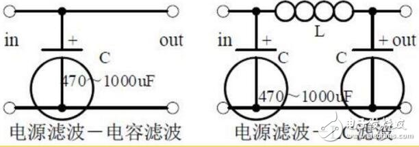
Points to note:
1. The process of power filtering and waveform formation;
2. Calculation: Selection of the capacity and withstand voltage of the filter capacitor.
Three, signal filter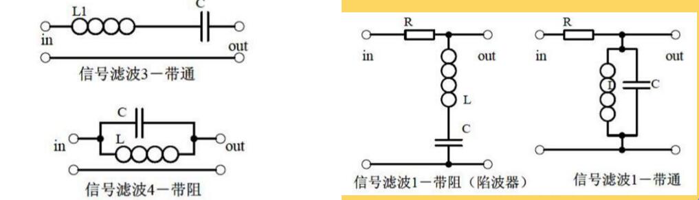
Points to note:
1. The function of the signal filter, the difference and similarities with the power filter;
2. Impedance calculation of LC series and parallel circuits, amplitude-frequency relationship and phase-frequency relationship curve;
3. Draw the passband curve and calculate the resonance frequency.
Fourth, the differential and integral circuit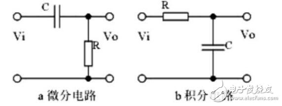
Points to note:
1. The function of the circuit, the difference and similarities with the filter;
2. Analyze the voltage change process of the differential and integral circuit, and draw the voltage change waveform diagram;
3. Calculation: time constant, voltage change equation, selection of resistance and capacitance parameters. 1 The role of the circuit: Integral circuit:
Five, differential and integral circuit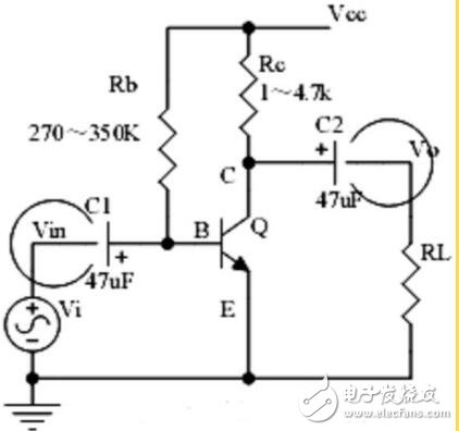
Points to note:
1. The structure of the triode, the current relationship between each pole of the triode, the characteristic curve, and the amplification conditions;
2. The role of the components, the purpose of the circuit, the voltage amplification factor, the phase relationship of the input and output signal voltage, and the AC and DC equivalent circuit diagrams;
3. Calculation of static operating point and voltage magnification.
Six, voltage division offset common emitter amplifier circuit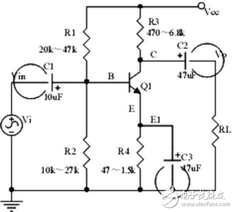
Points to note:
1. The role of the components, the purpose of the circuit, the voltage amplification factor, the phase relationship of the input and output signal voltage, and the AC and DC equivalent circuit diagrams;
2. Analysis of the negative feedback process of current series, and the influence of negative feedback on circuit parameters;
3. Calculation of static operating point and voltage magnification.
7. Common collector amplifier circuit (emitter follower)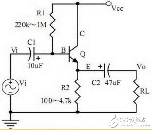
Points to note:
1. The role of the components, the purpose of the circuit, the voltage amplification factor, the phase relationship of the input and output signal voltage, and the equivalent circuit diagram of AC and DC. The input and output impedance characteristics of the circuit;
2. Analysis of the negative feedback process of current series, and the influence of negative feedback on circuit parameters;
3. Calculation of static operating point and voltage magnification.
8. Circuit feedback block diagram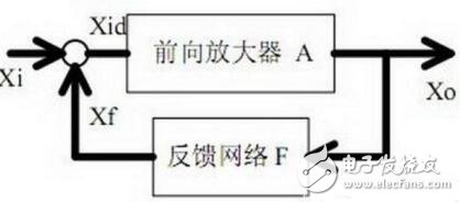
1. The concept of feedback, positive and negative feedback and its judgment method, parallel feedback and series feedback and its judgment method, current feedback and voltage feedback and its judgment method;
2. Amplification gain with negative feedback circuit;
3. The influence of negative feedback on the circuit's amplification gain, passband, gain stability, distortion, input and output resistance.
Nine, diode voltage regulator circuit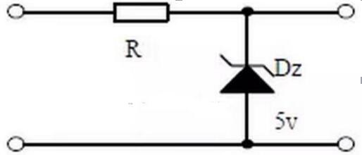
1. The characteristic curve of Zener diode;
2. Precautions for application of Zener diode;
3. Process analysis of voltage stabilization.
10. Series regulated Power Supply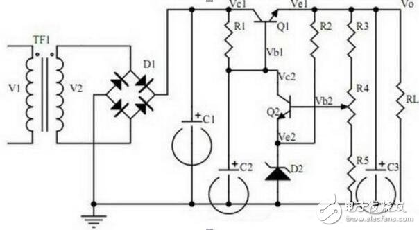
1. The concept of feedback, positive and negative feedback and its judgment method, parallel feedback and series feedback and its judgment method, current feedback and voltage feedback and its judgment method;
2. Amplification gain with negative feedback circuit;
3. The influence of negative feedback on the circuit's amplification gain, passband, gain stability, distortion, input and output resistance.
11. Differential amplifier circuit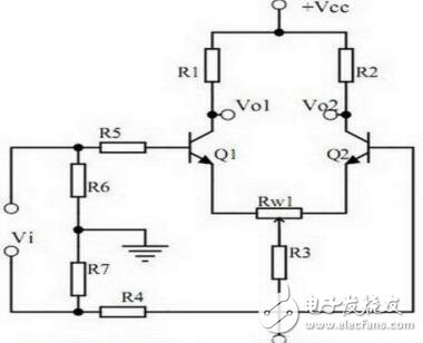
1. The role of the components of the circuit, the purpose of the circuit, and the characteristics of the circuit;
2. Analysis of the working principle of the circuit. How to amplify differential mode signals and suppress common mode signals;
3. The circuit's single-ended input and double-ended input, single-ended output and double-ended output working mode.
12. Field effect tube amplifier circuit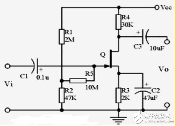
Points to note:
1. The classification, characteristics, structure, transfer characteristics and output characteristic curves of field effect transistors;
2. The characteristics of the field effect amplifier circuit;
3. Application occasions of field effect amplifier circuit.
13. Frequency selective (bandpass) amplifier circuit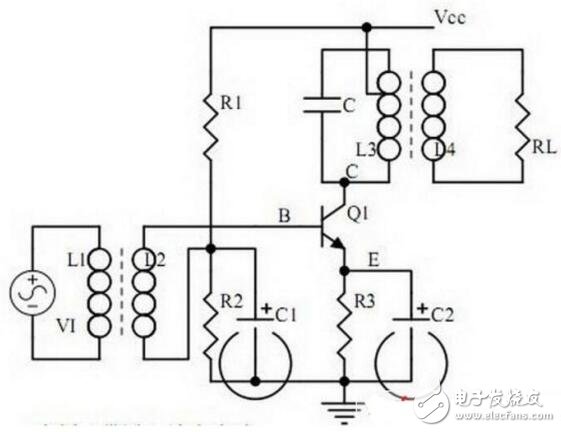
Points to note:
1. The role of each component, the characteristics of the frequency-selective amplifier circuit, and the role of the circuit;
2. Calculation of characteristic frequency and selection of frequency-selective component parameters.
14. Operational amplifier circuit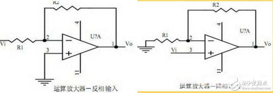
1. The concept of an ideal operational amplifier. The difference between virtual short circuit and virtual open circuit at the input end of the op amp;
2. The main purpose of the op amp circuit with inverting input mode, and the phase of the input voltage and output voltage signal;
3. Gain expression (input impedance, output impedance) under non-inverting input mode.
15. Differential input operational amplifier circuit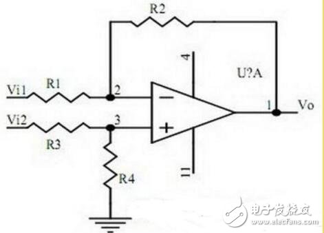
Points to note:
1. Features and uses of differential input operational amplifier circuit;
2. The relationship between output signal voltage and input signal voltage.
16. Voltage comparison circuit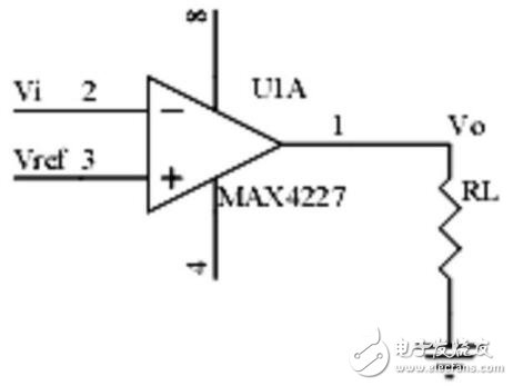
Points to note:
1. The function and working process of the voltage comparator;
2. The input-output characteristic curve of the comparator.
17. RC oscillator circuit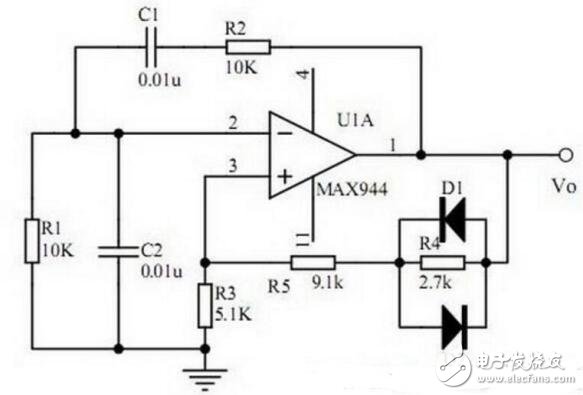
1. The composition, function, phase conditions of the oscillation circuit and the conditions of oscillation and balance amplitude of the oscillation circuit;
2. The relationship curve between RC circuit impedance and frequency, phase and frequency;
3. Phase condition analysis and oscillation frequency of RC oscillator circuit.
18. LC oscillator circuit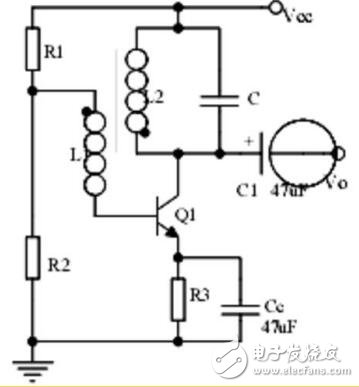
Points to note:
1. Oscillation phase conditions;
2. Calculation of oscillation frequency.
19. Quartz crystal oscillator circuit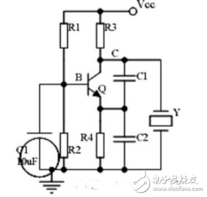
Points to note:
1. The characteristics, equivalent circuit and characteristic curve of quartz crystal;
2. Features of quartz crystal vibrator;
3. The oscillation frequency of the quartz crystal vibrator.
Twenty, power amplifier circuit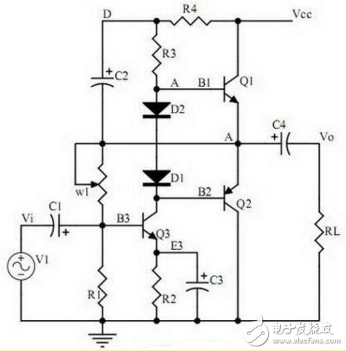
Points to note:
1. Working process and crossover distortion of Class B power amplifier;
2. The compound rule of compound triode;
3. The working principle and bootstrapping process of Class A and B power amplifiers, the characteristics of Class A power amplifiers and Class A and B power amplifiers.
Guangzhou Lufeng Electronic Technology Co. , Ltd. , https://www.lufengelectronics.com