Voltage Controlled Oscillator (VCO for short) is an important part of RF circuits. It is widely used in many fields such as communications, electronics, aerospace, aerospace, and medicine. It is especially important in amplifier circuits of communication systems. The essential key parts of the status.
With the development of electronic information systems such as modern communications, radar, electronic interference, and electronic reconnaissance using new systems, new technologies, new materials, and new processes, the demand for VCOs for electronic devices and their key components is also increasing, and VCOs are The frequency offset phenomenon occurs when the termination is under different load impedances. As a result, the operation of the electronic device is unstable or even fails and has a serious impact. Therefore, the nonlinear characteristics (such as frequency pull-in) test problem of the VCO is solved and the optimal matching is thereby achieved. It is increasingly important and urgent.
Nonlinear characteristics of VCOA Colpitt voltage-controlled oscillator in a typical bipolar transistor die package is used as an example, as shown in Figure 1. As can be seen from the figure, according to the basic principle of the oscillator, it consists of a resonant circuit, an active device, and an output load. The tuning voltage (Vcontrol) is input from the left end of the circuit. The resonant circuit includes a varactor Cvar, a resonant inductor L1, and capacitors C1, C2, C3, C4, and C5. The varactor is a type of reverse biased PN junction. A diode that generates a capacitance change is used to change the capacitance of the oscillator to achieve an adjustable output frequency; the active device is a bipolar transistor to amplify the oscillating signal; the output load is a part to which the oscillation signal is applied, and the ideal state is 50 ohm load.
When the selected resonant tank device satisfies the oscillator starting condition, the oscillator starts to work. The energy provided by the negative resistance portion of the active device in the VCO can satisfy the energy consumed by the resonant circuit. The oscillation condition of the oscillator circuit can be satisfied. It can be maintained and the VCO can work normally.
However, the actual working state of the VCO is not an ideal state, and it is not an ideal 50-ohm load that the terminal assumes in designing when it is designed. Therefore, a change in the terminal load condition causes a nonlinear phenomenon in which the output oscillation frequency of the VCO changes. Frequency traction, the characterization parameters for the frequency traction coefficient. As can be seen from Figure 1, the change in impedance seen from the VCO output causes a change in the DC voltage at the VCO's active device junction. That is, the signal power reflected from the VCO output can cause transistor leakage currents and bias points. The fluctuation causes the voltage (Vcb) between the collector and the base of the bipolar transistor to change, affecting the capacitance between the collector and the base (Ccb), and thus causing the oscillation frequency by affecting the resonance state and condition of the entire loop. And phase noise changes.
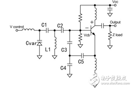
Figure 1. Typical bipolar transistor VCO model
solutionThe traditional test method is to connect the 6dB attenuator, directional coupler and mechanical tensile wire at the output end of the tested VCO. On the one hand, it meets the load conditions of 12dB return loss of the terminal connection, and on the other hand, it manually adjusts the mechanical tension. The line achieves a 360-degree phase change. However, this method has the following problems:
1 High dependence on the operator's ability;
2 time-consuming and laborious;
3 that the VCOs corresponding to different oscillation frequencies need mechanical tensile lines and open/short circuits corresponding to the working frequency band to avoid the phenomenon that the phase adjustment range cannot meet the requirements;
4 The model of the load impedance reflection coefficient is fixed and cannot be flexibly adjusted. Therefore, neither the test efficiency nor the test results can meet the increasingly high test requirements.
CECT adopts advanced load traction test technology to launch application solutions based on universal test instruments. The test block diagram is shown in Figure 2, which makes this situation effectively improved and thoroughly solves test problems.
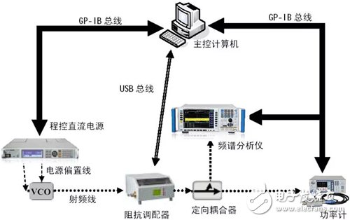
Figure 2. Block Diagram of VCO Nonlinearity (Frequency Traction) Test
Among them, the 176X series main flow control DC power supply products of the CLP instrument can provide the bias power supply and tuning voltage under program control for the tested VCO; the 243X series power meter products can measure the output power parameters of each test point under program-controlled state; 4051X Series spectrum analyzer products can measure the output frequency spectrum or frequency parameters of each test point under program control; directional coupler implements separate signals to provide test signals to power meter and spectrum analyzer respectively; automatic impedance adaptor is equivalent in programmed state The reflection coefficient mode (ie, return loss 12dB, VSWR 1.67) or other reflection coefficient circle of the required value adjusts the phase at equal intervals within 360o to achieve accurate and controllable change of load impedance; the main control computer and system software is the entire system. The control center, on the one hand, realizes the program control of various instruments and equipments in the system and coordinates each instrument and equipment to complete the collection and preservation of test data according to the test procedure. On the other hand, the data according to the calibration of the automatic impedance adaptor is cascaded according to the S-parameters. And related algorithms calculate the reflection coefficient and removal of the equivalent network Each part after insertion loss of the output power and other parameters. All testing work does not require human intervention, and the test can be automatically completed and the corresponding test results output when the conditions and conditions are set appropriately.
Applications 
Figure 3, HE405

Figure 4, HE486
This solution was applied to two types of TO-8C VCOs: HE405 (frequency range 1~2GHz, appearance as shown in Figure 3) and HE486 (frequency range of 2~3GHz, appearance as shown in Figure 4) developed by China Electronics XX. Tests are conducted to test the frequency deviation when the phase of the termination load impedance along the equal reflection coefficient circle is changed uniformly within 360o at different working frequencies. The test results are as follows:
1 The maximum frequency deviation of the HE405 at the operating frequency of 1.6 GHz is 24.433334 MHz, ie, the frequency traction coefficient is 1.53% @ 1.6 GHz; the maximum output power offset is 1.10 dB, and the output power is 16.00 dBm at this time. The test curve is shown in Figure 5 below, where the ordinate is the operating frequency test value (Hz), and the abscissa is the test point when the load impedance phase is uniformly changed in the 360° range of equal reflection coefficient circles (the test result contains a total of 36 points) .
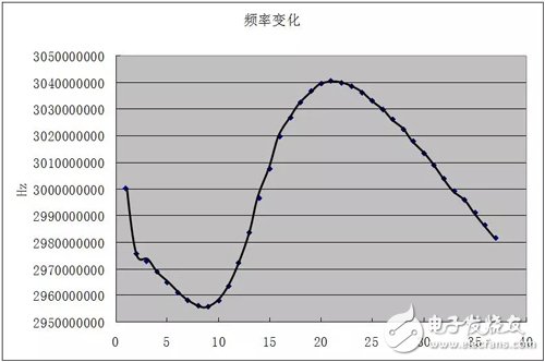
Fig. 5 Nonlinear characteristic (frequency pull) test curve of HE405 operating frequency at 1.6GHz
2 The maximum frequency deviation of the HE405 at the operating frequency of 2GHz is 24.666666MHz, ie, the frequency traction coefficient is 1.23%@2GHz; the maximum output power shift is 1.95dB, and the output power is 15.03dBm. The test curve is shown in Figure 6 below, where the ordinate is the operating frequency test value (Hz), and the abscissa is the test point when the load impedance phase is uniformly changed within a 360o range of equal reflection coefficient circles (the test result contains a total of 36 points). .
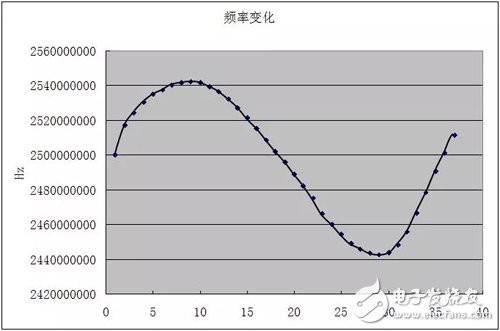
Figure 6. Nonlinear characteristics (frequency pull-off) test curve of the HE405 operating frequency at 2 GHz
3 The maximum frequency deviation of the HE486 at the operating frequency of 2.5GHz is 42.000000MHz, ie the frequency traction coefficient is 1.68% @ 2.5GHz; the maximum output power shift is 2.15dB, and the output power is 16.70dBm at this time. The test curve is shown in Figure 7 below, where the ordinate is the operating frequency test value (Hz) and the abscissa is the test point when the load impedance phase is uniformly changed within a 360o round of the iso-reflectivity circle (the test result contains a total of 36 points). .
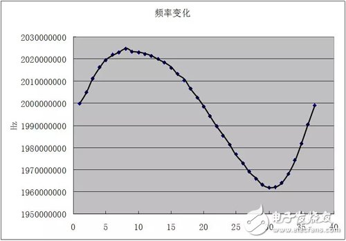
Figure 7. Nonlinear characteristics (frequency pull-off) test curve of 2.5GHz working frequency of HE486
4 The maximum frequency deviation of the HE486 at the operating frequency of 3GHz is 40.4000000MHz, ie, the frequency traction coefficient is 1.35%@3GHz; the maximum output power offset is 1.30dB, and the output power is 14.46dBm at this time. The test curve is shown in Figure 8 below, where the ordinate is the operating frequency test value (Hz) and the abscissa is the test point when the load impedance phase is uniformly changed within 360o of the iso-reflectivity circle (the test result contains a total of 36 points). .
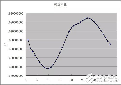
Fig. 8. Nonlinear characteristics (frequency pull-off) test curve of HE486 operating frequency at 3GHz
Through comparison with the technical indicators developed by the institute on these two types of VCOs, the test has achieved satisfactory results, indicating that the application solution of the CLP instrument is not only simple and easy to operate, but also displays in terms of test efficiency, test consistency, etc. Outstanding advantages can meet the test requirements of nonlinear characteristics (frequency traction) in the current VCO development, production, and other processes, and have a good application prospect.
Budget Laptop For Students is a great gift parents like to prepare for their children. There are too many choices on the market, so how to choose a right one for your children? 10.1 inch Low Budget Laptop For Students is design for kids, like below 10 years; 14.1 inch n4020 64gb Budget Friendly Laptops For Students is the most competitive and hot one for student project; 15.6 inch n5095 128gb Budget Friendly Laptops For Students is the best one for middle or high school student or teacher online teaching; Of course, also have High Quality Cheap Laptops with i3, i5, i7 10th or 11th; 15.6 inch or 16.1 inch i7 Affordable Laptop With Good Specs and dedicated graphics. Other 11.6inch celeron budget friendly laptops in 2 in 1 or yoga type also available.
Therefore, you can share your recent and powerful hardware interest, then we can recommend the right one for you. Of course, can customize as your special requirements.
In fact, the most easiest way is what you share the details, like size, cpu, ram, rom, pcs, oem service, screen, camera, etc.
Budget Laptop For Students,Low Budget Laptop For Students,Budget Friendly Laptops For Students,Affordable Laptop With Good Specs,High Quality Cheap Laptops,Budget Friendly Laptops
Henan Shuyi Electronics Co., Ltd. , https://www.shuyielectronics.com