When the infrared remote controller transmits data, the binary data is modulated into a series of pulse signals and transmitted by the infrared transmitting tube. The infrared carrier is a square wave with a frequency of 38KHz, and the infrared receiving end outputs a low level when receiving the carrier signal of 38KHz. Otherwise, the output is high, so that the "intermittent and continuous" infrared light signal can be demodulated into a continuous square wave signal of a certain period, and then the original data signal can be recovered after demodulation by the 1838 integrated infrared receiving head. As shown in Figure 1
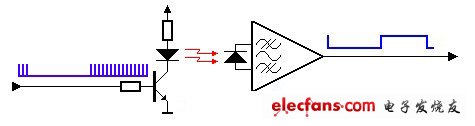
figure 1
The infrared receiver head demodulation process is shown in Figure 2.
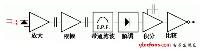
figure 2
The demodulated "0" and "1" waveforms and the single-chip code are shown in Figure 3 and Figure 4.
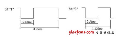
image 3
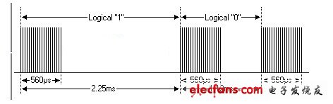
Figure 4
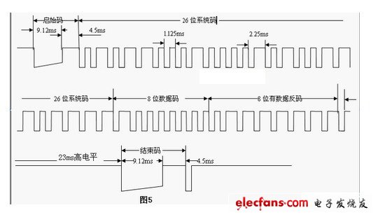
Figure 5
Understand the infrared receiver head demodulation and remote control coding. The code program can be written according to Figure 5. Figure 5 is a section of the actual code of the remote control button 1, starting from 9ms low 4.5ms high level, 26-bit system Code, and 8-bit data code, 8-bit data inverse code, 23ms high level and end code.
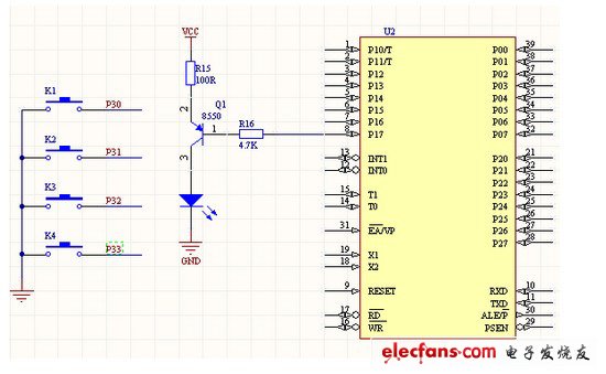
Circuit diagram
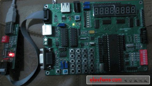
Physical map
Ring And Fork Type Insulated Terminals
Taixing Longyi Terminals Co.,Ltd. , https://www.longyicopperlugs.com