Household inverter circuit (3)
Circuit working principle:
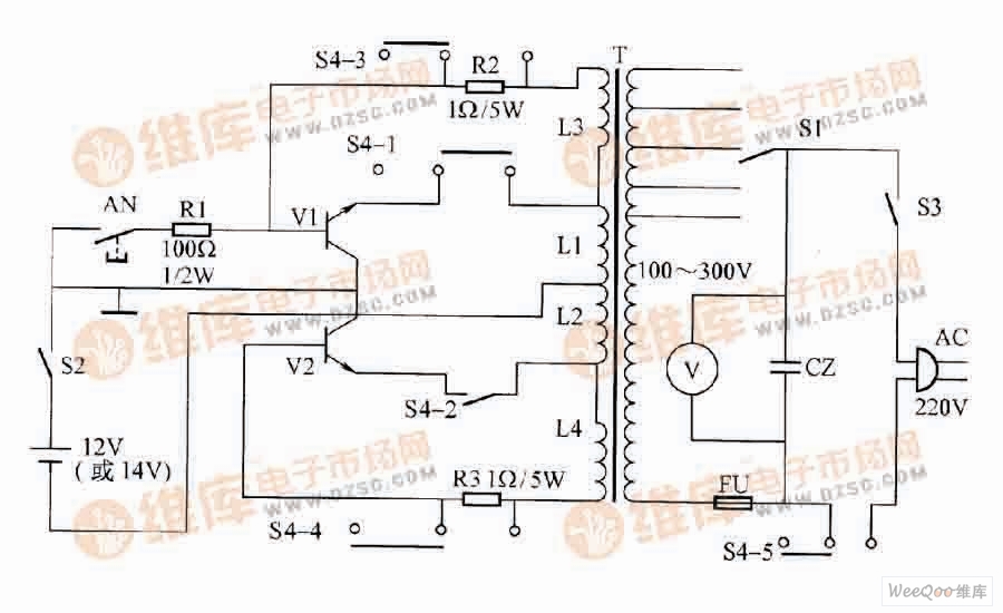
(1) Inverter working state: The windings of the inverter Power Transformer are divided into two groups. Group A is a primary winding when inverting, and is powered by a battery; Group B is an AC output winding, and an external electrical appliance is used. After the power is turned on, the positive and negative terminals of the battery are respectively applied to the collector and emitter of the two transistors. The positive terminal is applied to the base of the two transistors through a resistor, so that the bases of the two tubes are simultaneously positively biased. Since the circuit is not completely symmetrical, the timing of the conduction of the two transistors is always sequential. Assuming that the V1 tube is turned on first, and its collector current passes through the winding L1, the other groups of windings simultaneously generate an induced electromotive force with a polarity of up and down. The negative terminal of the induced electromotive force of the winding L4 is connected to the base of V2, so that V2 is in an off state. The positive terminal of the induced electromotive force of the winding L3 is connected to the base of V1, so that the conduction of V1 is deepened and rapidly enters a saturated state. This is a positive feedback process, in which the voltage of the battery is almost entirely applied to the winding L1.
The current flowing through the L1 winding increases in magnetic flux generated in the closed core magnetic circuit of the transformer at a proportional speed. When the magnetic flux density reaches saturation, the collector current increases sharply, and the change in magnetic flux is approximately zero, and the induced electromotive force of each winding of the transformer also tends to zero. The decrease of the induced electromotive force of L3 causes the current of the V1 base to decrease, and the collector current also decreases, so that the induced electromotive force generated by each winding changes direction, that is, the upper and lower positive. Then the core flux density exits the saturation region, and then the positive feedback process happens to make V1 cut off quickly, V2 is rapidly saturated and turned on, and the battery voltage is almost entirely applied to the winding L2.
The alternating turn-on and turn-off of the two transistors is equivalent to artificially feeding the variable voltage into the primary winding, and the secondary winding will obtain the increased alternating voltage in this ratio.
(2) Charging working state: When the charging one inverter switch S4 is placed in the charging position, the inverter is converted into a rectifier. At this time, the mains power input from the AC plug is supplied to the household appliance, and the voltage is controlled by the voltage regulating switch S1 to the winding of the group B of the transformer. As can be seen from the schematic diagram, at this time, the emission stages of the two transistors are disconnected, S4-3, S4-4 short-circuit the resistors R2 and R3, and the b-e junction of the two transistors and the group A winding of the transformer constitute a full-wave rectifier circuit. , charge the battery. Rotating the position of S1 can change the magnitude of the charging current (S1 can select the level of the output voltage when inverting).
Component selection:
The transistor adopts 3DD15 high-power tube, which requires reverse withstand voltage greater than lO0V, saturation voltage drop less than 1V, DC amplification factor greater than 80; start resistor R1 uses 1/2W or more metal film resistor, and the resistance value is selected between 50 and 200Ω. The smaller the value, the easier it is to start the vibration; the base resistance can be more than 5W cement resistance or more than 500W electric furnace wire, the resistance value is 0.5~2Ω; the cross-sectional area of ​​the transformer core is proportional to the power of the inverter power supply, the size is: 100W 13cm2, 150W is 15cm2, 200W is 17.5cm2, 300W is 22.5cm2; battery is used 12V or 14V battery; battery A·h is user-selected, there is no upper limit, and 10A·h is the lower limit.
For the 33kV Oil Immersed Power Transformer, we can produce capacity upto 50MVA. We use the best quality of raw material and advance design software to provide low noise, low losses, low partial discharge and high short-circuit impedance for power transformer.
Our power transformer are widely used in national grid, city grid, rural grid, power plant, industrial and mining enterprise, and petrochemical industry.
Conventer Transformer,33Kv Power Transformer,33Kv Power Transformer With Octc,Power Transformer With Octc
Hangzhou Qiantang River Electric Group Co., Ltd.(QRE) , https://www.qretransformer.com