The industrial X-ray flaw detector delay control switch introduced in this example can delay the 30s start exposure system. In this way, the staff can use this 30s time to quickly leave the X-ray flaw detector to reduce the absorbed dose of X-rays and prevent X-rays from damaging the health of the body.
Circuit Operation Principle The industrial X-ray flaw detector delay control switch circuit consists of a voltage regulator filter circuit, a delay control circuit A, a delay control circuit B and a control execution circuit, as shown in Figure 8-150. 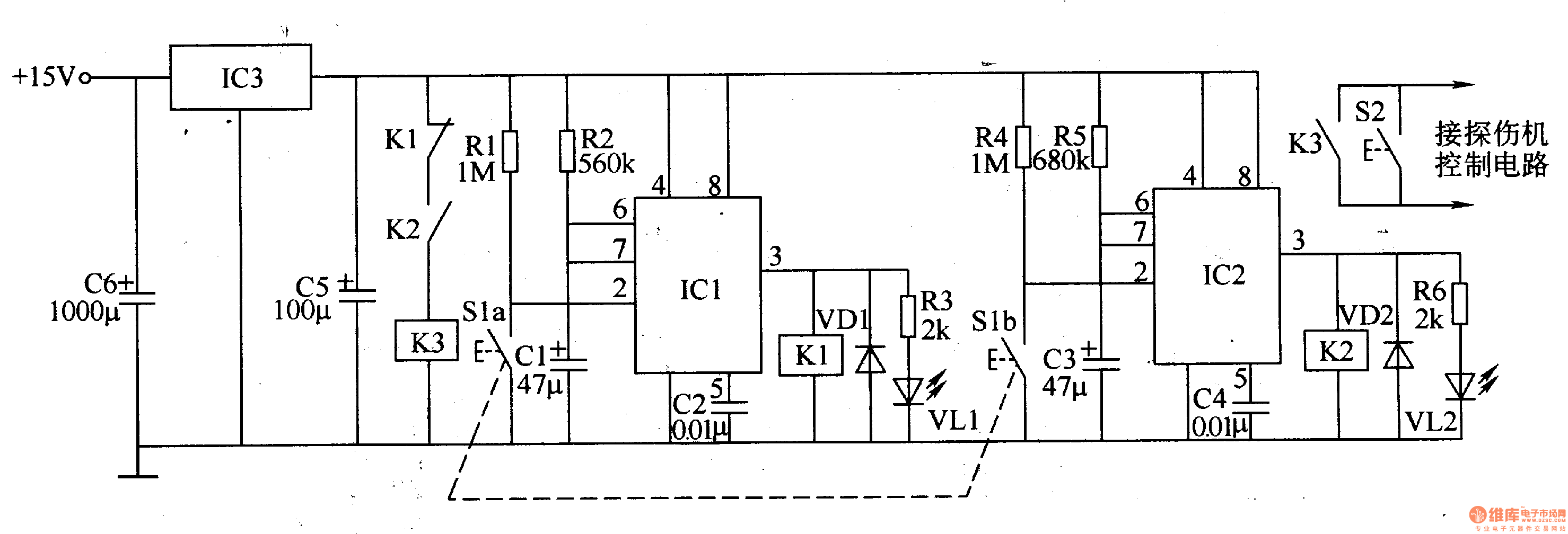
The voltage regulator filter circuit is composed of capacitors C5 and C6 and a three-terminal voltage regulator integrated circuit lC3.
The delay control circuit A is composed of resistors R1-R3, capacitors C1, C2, time base integrated circuit ICl, diode VD1, relay K1, light-emitting diode VLl and control button S1.
The delay control circuit B is composed of resistors R4-R6, capacitors C3, C4, time base integrated circuit 1C2, diode VD2, relay K2, light-emitting diode VL2, and control button S1b.
The control execution circuit is composed of normally closed contacts of relays K3 and K1, normally open contacts of K2, and high voltage button S2.
IC1 and IC2 form two monostable flip-flops with external RC components, respectively. Normally (when S1 is pressed at the end), both pins 1C and 1C2 output low level. When S1 is pressed, Sla and Slb are turned on, so that the 2 pins of lCl and IC2 become low level, the monostable flip-flop flips into the transient state, the 3-pin outputs the high level, the relay Kl and the saturation are all energized. When VLl and V忱 are both lit, the normally closed contact of Kl is disconnected, and the normally open contact of K2 is turned on; at the same time, Cl and C3 are charged by R2 and R5, respectively. When the voltage at both ends of Cl is charged to 8V (about 30s), the circuit inside ICI is reversed, and the transient is restored to steady state, 3 feet are changed to low level, VLl is extinguished, Kl is released, and its normally closed contact is turned on, K3 When the power is applied, the normally open contact of K3 is turned on (equivalent to pressing the high voltage button S2), and the exposure circuit is energized. After 8s delay, IC2 also flips to steady state, its 3 feet become low level, VL2 is extinguished, K2 and K3 are released, and one exposure ends.
Component selection
Rl-R6 uses 1/4W metal film resistor or carbon film resistor.
Cl, C3 and C5 are all made of aluminum electrolytic capacitors with a withstand voltage of 16V; C2 and C4 are made of monolithic capacitors or polyester capacitors.
Both VDl and VD2 use the lN4007 silicon rectifier diode.
Both VLl and VU use φ5mm LEDs.
Both lCl and IC2 use NE555 type time base integrated circuits.
Kl-K3 selects 4098 or JZC-23F, JRX-l3F type 12V DC relay.
The S1 uses a small push button; the S2 still uses the high voltage switch on the panel of the original flaw detector.
Our lithium battery includes 5G Base Station Backup Power System,like 48V 100Ah/150Ah/200Ah Lithium Battery. 3.2V Prismatic cells,like 3.2V 50Ah/105Ah/202Ah Lithium Battery. And Lithium Ion Pouch Cells, including 3.2V 12-30Ah.
Lifepo4 Battery,Lifepo4 Lithium Ion Battery,Lifepo4 48V 100Ah Lithium Ion Battery,Lithium Ion Battery For Solar 100Ah
Jiangsu Zhitai New Energy Technology Co.,Ltd , https://www.zt-tek.com