0805 red light emitting diode
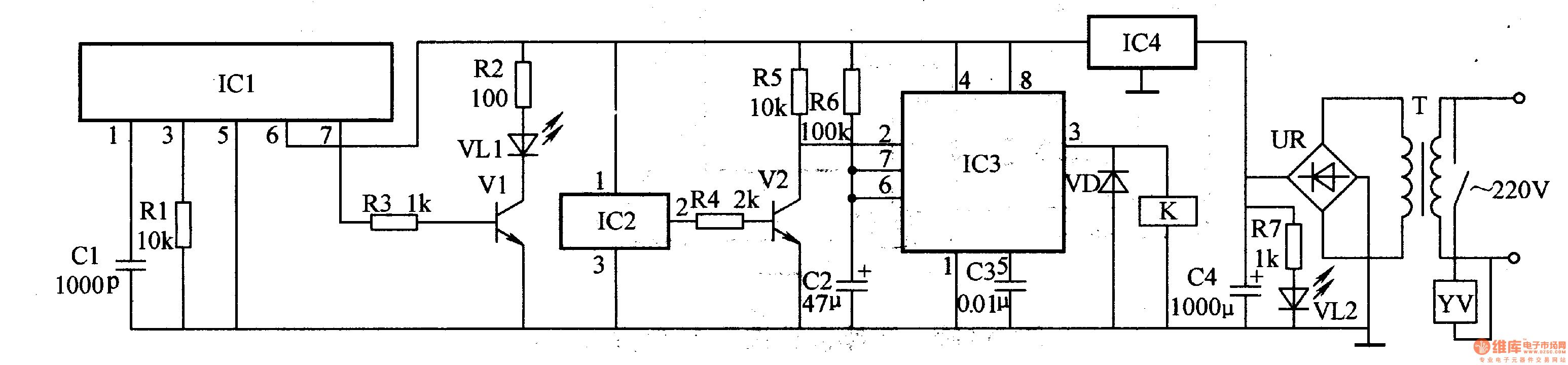
The power circuit is composed of a power transformer T, a rectifier bridge stack UR, a filter capacitor C4, a current limiting resistor R7, a power indicating LED VL2, and a three-terminal voltage regulator integrated circuit IC4.
The infrared transmitting circuit is composed of an infrared emitting integrated circuit ICl, a resistor Rl-R3, a capacitor C1, a transistor Vl and an infrared light emitting diode VLl.
The infrared receiving and amplifying circuit is composed of an integrated infrared receiving integrated circuit IC2, resistors R4 and R5 and a transistor V2.
The delay control circuit is composed of a time base integrated circuit IC3, a resistor R6, capacitors C2, C3, a diode VD and a relay K.
After AC 220V voltage is stepped down by T, UR rectified and C4 filtered, VL2 will be lit after one R7 current limit; the other is secondarily regulated by IC4 to +6V, as infrared transmitting circuit, infrared receiving amplifying circuit and delay The operating power of the control circuit.
The infrared transmitting circuit is oscillated after being energized, and the 7-pin of IC1 outputs an oscillation signal of 38 kHz. After the signal is amplified by V1, the VLl is driven to modulate the infrared light.
IC2 receives the infrared light emitted by VLl and processes it, and outputs a low level from pin 2 to make V2 cut off, pin 2 of lC3 becomes high level, pin 3 outputs low level, K is in release state, YV Is off.
When the hand is extended under the hand washing device, the infrared light emitted by the VLl is blocked by the hand, IC2 can not receive the infrared signal, and the 2 pin outputs a high level, so that the V2 is saturated and the 2 pin of the lC3 becomes the low level. 3 feet output high level, so that K is energized, K's normally open contact is connected to YV's working power supply, and YV is energized to discharge water. When the water is used and the hand is removed from the hand washing device, IC2 receives the infrared light emitted by VL1, V2 is turned off, the 2 pin of IC3 becomes high level, the 3 pin becomes low level, K is released, and YV is turned off.
Component selection
Rl-R7 uses 1/4W metal film resistor or carbon film resistor.
Cl uses high-frequency ceramic capacitors or glass glaze capacitors; C2 and C4 select aluminum electrolytic capacitors with a withstand voltage of l6V; C3 uses monolithic capacitors or polyester capacitors.
VD selects 1N4007 silicon rectifier diode for use.
VLl selects PH303 type infrared light-emitting diode; VL2 selects p3mln green high-brightness light-emitting diode.
UR selects the rectifier bridge stack of lA and 5OV.
Vl and V2 select S9013 or 3DG9013 type silicon NPN transistor.
ICl selects HG-111F type infrared transmitting integrated circuit; IC2 selects three-terminal integrated infrared receiving head, such as FPS-4091; lC3 selects NE555 type time base integrated circuit; IC4 selects LM7806 type three-terminal steady-state integrated circuit.
K selects JRX-l3F type 6V DC relay.
T uses a power transformer of 1.5-3W and a secondary voltage of 9V.
W selects DF-l type AC 220V electromagnetic water valve.
Ring And Fork Type Insulated Terminals
Taixing Longyi Terminals Co.,Ltd. , https://www.txlyterminals.com