The terminal controller mainly implements two functions. First, the integrated camera and the pan/tilt are controlled according to the instructions of the main controller. First, the voice signal of the current classroom is collected and processed and uploaded.
Camera and pan/tilt control circuit and implementation: Receive control command of RS485 control bus through MAX485 and control relay group action according to command to realize zooming, zooming/nearning of upper, lower, left and right rotation and aperture motor of PTZ motor Light/dark adjustment. The chip MC145027 is used to complete the decoding of the MCU instruction. The MCU sends the address command to the terminal controller. The control of the terminal controller sends the data command. Only when the address command sent by the MCU is the same as the address set by the MC145027, the MC145027 receives the data command of the MCU, that is, the control command. Thereby an addressable individual control for each terminal is achieved.
Matrix switcher circuit
The system is designed to monitor the capacity of 32 channels of audio and video. To simplify the design, and to facilitate the debugging, installation and upgrade, 32 channels of audio and video are not processed on one PCB, but are divided into 4 sub-boards, each block The N8 road audio and video at the board realizes the 8-to-1 output function of the 8-channel audio and video channel, that is, the four sub-boards form a matrix switcher, and realize the 32-select 4 output function at the same time. The circuit diagram of each daughter board is shown in Figure 3.
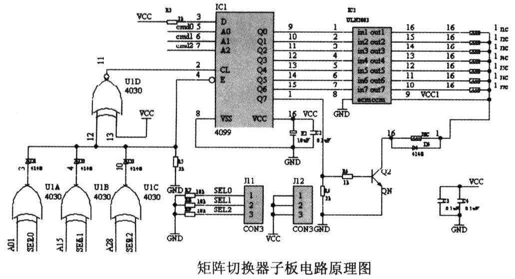
In Fig. 3, J1...J8 are relay coils, and the double-pole double-throw relay J4078 realizes simultaneous switching of audio and video. J11 and J12 are jumper sockets. The jumper sets the address for the daughter board. When the set sub-board address is the same as the sub-board selection address (A0, A1, A2) of the main controller, the 4099 of the sub-board is in working state. At this time, through the channel selection command (cmd0, cmd1, cmd2) of the main controller, any relay in J1...J8 can complete the switching action to realize the simultaneous strobe of a certain channel of audio and video.
Speech signal acquisition and processing circuit
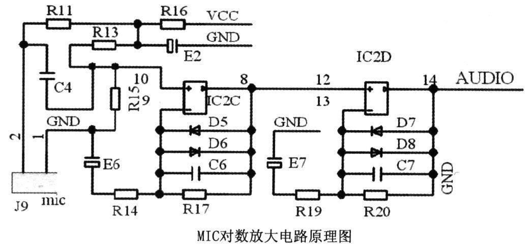
Because the voice signals of various positions in the classroom (generally in the range of 20~50m2) are collected, it is obviously impossible to use ordinary microphone amplifying circuits. The system adopts a logarithmic amplifying circuit for voice amplification, and relatively clearly collects voice signals at various positions within a range of 50 m 2 . The logarithmic amplification circuit designed is shown in Figure 5. IC2 is an operational amplifier, and the system uses LM358 to achieve two-stage operational amplification.
The use of sensing technology and electronic technology system design ideas are simple, low cost, convenient and practical. It plays a very important role in improving students' self-awareness, monitoring the operation of independent learning equipment and software platforms, preventing unnecessary damage caused by human damage, and improving the stability and reliability of equipment operation.
Machining Parts
Shaft sleeve connector
Shaft sleeve connector
Material: stainless 304
Surface: ultrasonic wave cleaning, passivating
Tube connector
Material: GB20
Surface: trivalent chromium zinc coating
Application: fixed end for control system assembly
Tube guide threaded
Material: stainless 304
Surface: ultrasonic wave cleaning, passivating
Application: control system in Yacht
Control Shaft,Tube Connector,Tube Guide Threaded,Shaft Sleeve Connector
ROYAL RANGE INTERNATIONAL TRADING CO., LTD , https://www.royalrangelgs.com