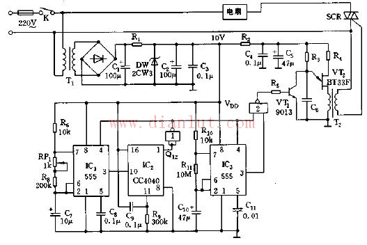
A low frequency multi-resonator IC3 and NAND gate 2 are added as shown. From the graphical parameters, the IC3 oscillation frequency works at very low frequencies, the operating frequency is about 0.05 Hz, and the duty cycle is 50%. When the power switch is turned on, since Q2 (1 pin) of IC2 is low electronic flat "0", it is added to IC1 and IC3 pin 4 via inverter, both 555 start to oscillate, and NAND gate 2 is turned on. VT1 is cut off, VT2 is oscillating, SCR is triggered to turn on, and the fan is turned. But when the capacitor C10 charging time reaches: t1 = O.693 (Rl0 ten R11) C10.
Shelf LED Display,LED Shelf Display,LED Display Screen,Digital Signage Screen
ShenZhen UHLED Technology Co., LTD. , https://www.uhled.com