Circuit Operation Principle The negative oxygen ion generator circuit consists of a power circuit, a humidity detection circuit, an oscillator, and a high voltage generator, as shown in Figure 9-114.
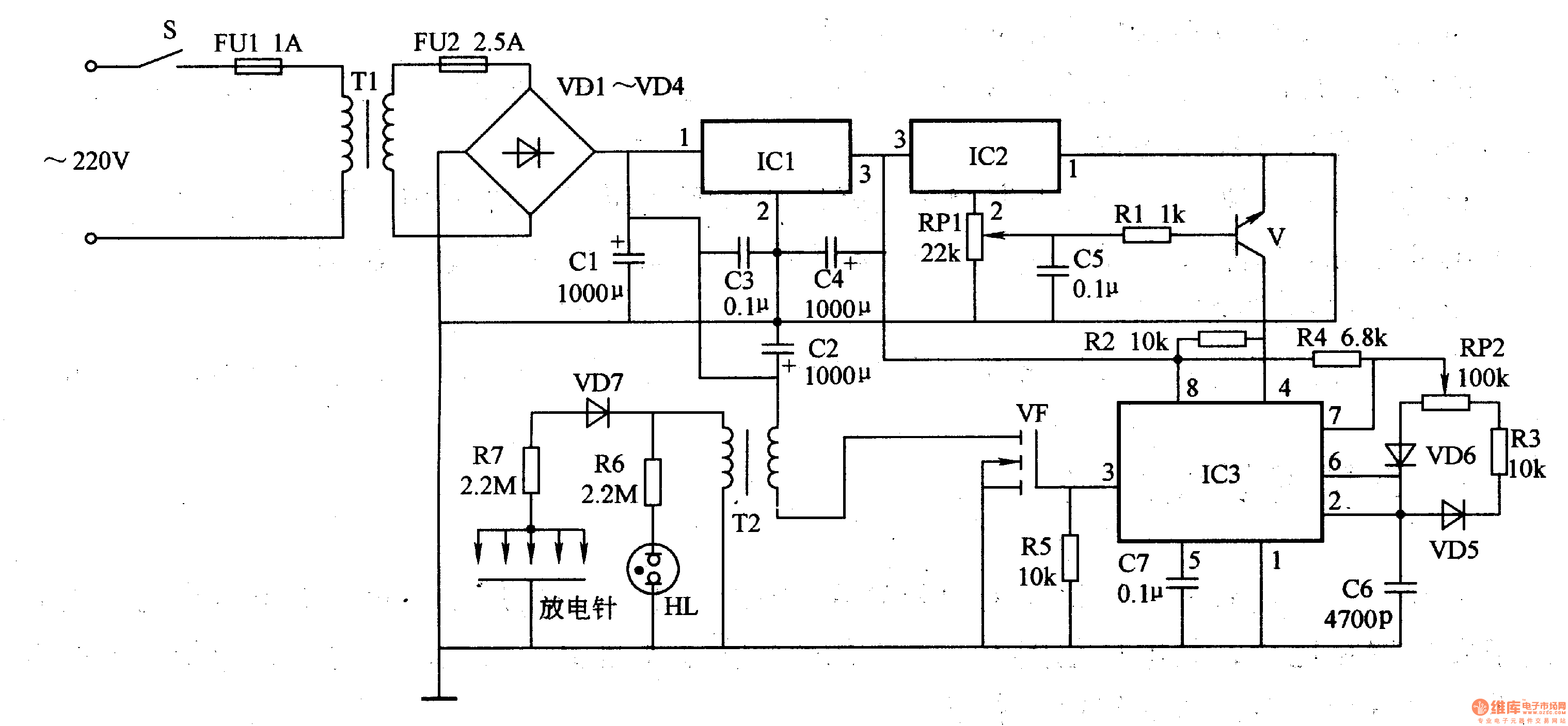
The power circuit is composed of a power switch S, a fuse FU1, a FU2, a power transformer Tl, a rectifier diode VD1-VD4, a filter capacitor Cl-C3, and a three-terminal integrated voltage regulator IC1.
The humidity detecting circuit is composed of an integrated circuit IC2, a control tube V, a potentiometer RP1, a resistor R1, and a capacitor C5.
The oscillator consists of a time base integrated circuit IC3 and peripheral components.
The high voltage generator circuit is composed of a field effect transistor VF, a step-up transformer T2, a rectifier diode VD7, a resistor R6, R7, a æ°– indicator light HL, and a discharge needle (discharge electrode).
After the power switch S is turned on, the AC 220V voltage is depressurized by Tl, rectified by VDl-VD4, and filtered by Cl-C3 to generate a hundred current voltage of about 18V. The voltage is supplied to VF through a saturated primary winding; the other is regulated to +5V by IC1, and is supplied to IC2, V and IC3.
When the indoor humidity is relatively small (less than 80%), IC2's 2-pin output voltage is lower, V is in the off state, IC3's 4 pin is high, the oscillator oscillates, and 2OkHz is output from IC3's 3 pin. The oscillating signal controls VF to operate in the switching state. A high-voltage pulse of 8-9kV is generated from both ends of the secondary winding of T2. After rectification by VD7, negative oxygen ions are generated through the discharge needle, and the indicator light HL is illuminated.
When the indoor relative humidity is large (more than 80%), in order to prevent the user from getting an electric shock, IC2's 2 pin outputs a high level, making V turn on, IC3's 4 pin goes high, the oscillator stops, IC3 The 3 pin has no oscillation signal output, the high voltage generating circuit does not work, and the indicator light HL does not light.
Adjusting the resistance of RPl can change the conduction sensitivity of V.
Adjusting the resistance of RP2 can change the operating frequency of the oscillator, thus changing the high voltage of the pulse.
Component selection
Rl-R6 selects 1/4W carbon film resistor for use; R7 selects 3-5W wirewound resistor for use.
RPl and RP2 use small solid potentiometers or sealed variable resistors.
Both Cl and C2 use aluminum electrolytic capacitors with a withstand voltage of 25V; C3, C5 and C7 use polyester capacitors or monolithic capacitors; C4 selects aluminum electrolytic capacitors with a withstand voltage of 16V; C6 uses high-frequency ceramic capacitors.
VDl-VD6 selects 1N4007 type silicon rectifier diode for use; VD7 selects 2DL15 type high voltage rectifier tube for use.
V selects S9014 or 2SC9014 type silicon NPN transistor.
VF uses BUZ380 high power field effect transistor.
ICl selects LM7805 type three-terminal voltage regulator integrated circuit; IC2 selects IH-3605 type humidity detection ASIC; IC3 selects NE555 type time base integrated circuit.
Tl selects 8-1OW, the secondary voltage is l5V buck power transformer. The full-size E-core winding is used: the primary winding is wound 30 åŒ with a φ0.3 mm enameled wire, and the secondary winding is wound with a φ O.1 mm enamel wire around 3500 åŒ.
HL selects the common æ°– indicator.
The discharge needle can use a large number of large sewing needles, and all the tail ends of the discharge needles are connected, and the needle tip is discharged to the ground (metal plate).
REMOTE CONTROL SOCKET
Important Safeguards
When using any electrical appliance, in order to reduce the risk of fire, electric shock and/or injury to persons, basic safety precautions should always be follow8d. including:
• The appliance is for household and indoor use only.
• Before plugging in. check that the voitage on the rating label is the same as the mains supply.
• To protect against electric shock, do not immerse any part of the product in water or other liquid.
• This socket is intended for use by competent adults only and children should be supervised at all times.
• Do not use the socket for other than its intended use.
• This socket can be used by children aged from 8 years arxl above and persons with reduced physical, sensory or mental capabilities or lack of experience and knowledge if they have been given supervision or instruction concerning use of the appliance in a safe way and understand the hazards involved. Children shall not p<ay with the appliance Cleaning and user maintenance shall M be made by children without supervision.
• Children of less than 3 years should be kept away unless continuously supervised.
Children from 3 years and less than 8 years shall only switch on/off the appliance provided that it has been placed or installed in its intended normal operating position and they have been supervision or instruction concerning use of the appliance in a safe way and understand the hazards involved. Children aged from 3 years and less than 8 years shall not plug in. regulate and clean the appliance or perform user maintenance.
• Don't use this socket in the immediate surroundings of a bath, a shower or a swimming pool.
• In case of malfunction, do not try to repair the socket yourself, it may result in a fire hazard or electric shock
Do Not Exceed Maximum a680W
Place the LR44 batteries provided into the compartment in the back of the Remote Control, please insert as sho*/m in the back of the compartment to ensure the polarity is correct.
Programming Instructions
• Plug the Remoce Socket$($)lnto the wall socket(s) and switch on the mams supply, the red LED will flash every second.
• If the LED is not flashing press & hold the manual ON/OFF button for 5 seconds until it Hashes
•Press any ON switch on the Remote Control for approximately 2 seconds and the Remote Socket(s) learn the code. The LED will stop flashing top confirm the codehas been accepted.
• Any number of Remote Sockets can be programmed to one Remote Control ON button to create multiple switching.
• To programme o<her Remote Sockets on different Remote Control ON buttons repeat the prevous steps
• If the mains supply is turned off the Remote Sockets v/ill lose their code and it wil be necessary to re-pcogramme.
Operation:
• Plug your appliance(s) into the Remote Socket(s)
• Press the programmed ON or OFF button on the Remote Control to control the Remote Socket.
♦ The Remote Sockets can also be operated manually using its ON/OFF Button Trouble shooting
If a Remote Socket does not react to the Remote Control please check the followng:
♦ Low battery in tbo Remote Control
• Distance too large between the remote control and the recerver (ensure the range distance is no more than 20 clear Metres) and free from obstacle that may reduce the distance.
• If programming has not been successful, tum the power off and back on then follow the programming steps above.
How to decode
• Press the manual ONX)FF button for 5 seconds until the red LED flashes once per
second to confirm de-coding is successful
♦ Press the ALL OFF switch on the Remote Control for more than 3 seconds, the LED
flashes once per second to confirm (decoding successful.
Voltage: 240V-/50HZ
Max power rating: 3680W max.
Remote frequency:
Remote range:
Battery Type:
433.92MHz
230 Metres
Button Cell 2x1.5V LR44 =
Please check with your local waste management service authority regarding regulations for the safe disposal of the batteries. The batteries should never be placed G municipal waste.
Use a battery d^posal facility if available
M
For eioctncal products sold within the European Community. At the end of the electrical products useful life, it should not be disposed of wth household waste. Please recycle faaMies exist. Check with your Local Authonty or retailer for recycling advice.
C€
Remote Control Plug Socket,Remote Controlled Mains Outlet,Remote Control Plug Adapters,Remote Control Sockets,Remote & Smart Controlled Sockets,Electric Sockets Plus Remote Control
NINGBO COWELL ELECTRONICS & TECHNOLOGY CO., LTD , https://www.cowellsockets.com