How far does it take to get from the radiation source so that the radiation signal does not interfere with the system? To understand the answer to this question, consider the following two questions: 1) the amount of radiant energy from the source; and 2) the performance of the system's EMI protection circuit.
A radiated electromagnetic interference (EMI) signal propagates from the source to a receiving unit. Fundamentally, the power or voltage strength of these signals depends on the transmitter's power/antenna gain and the distance between the source and receiver when "touching" sensitive circuits (see Figure 1).

Figure 1 EMI electric field and power density relationship between the radiation source and the receiver
Electric field strength or radiated power density parameters may be utilized for EMI evaluation. The electric field strength quantifies the magnitude of the interference voltage of the radiation source. This narrowband or wideband EMI signal is measured in volts per meter (V/m). You can modify this electric field strength unit according to your preference and convert them to dBμV/m, where dBμV = 20 log (V) + 120μV.
Narrowband EMI signals are typically repetitive signals or pulse sequences. Using the simple formula shown in Figure 1, an extreme estimate of the radiated voltage, Er, can be quickly calculated somewhere from the EMI source. Broadband EMI signals are typically a single pulse, such as lightning, an ESD event, or a spark gap. These pulse type events contain multiple frequencies. Wideband signals are difficult to measure because they are not repeatable and fast.
Radiant power density units can also be used to describe narrowband events. The measurement unit (radiation power density) of the EMI narrow band can be watts per square meter, ie W/m2. Communication engineers use power density to represent EMI signals to solve their narrow-band EMI problems. The radiated power density unit can be converted to dBm/m2, where dBm (dB milliwatts) = 10 log (W).
In the laboratory, EMI signals can be pre-analyzed in the time and frequency domains. The signal is time-domain observed using an oscilloscope, and then the frequency domain is evaluated using a spectrum analyzer. However, some companies that pass the Federal Communications Commission (FCC) and the European Special Commission for Europe (CISPR) radio interference certification must perform all radiated EMI measurements before the product goes on the market. This requirement ensures that the test results are fully compliant with FCC and/or CISPR regulations. Test methods include the use of environmental tests and the use of calibrated EMI test equipment and antennas. The FCC and CISPR require that the radiated signal emitted by the device must be below the specified value. The FCC and CISPR related documents include EN 55011, EN 55013, EN 55014, EN 55015, EN 55022 and EN 50081-1.2 (General Radiation Standards).
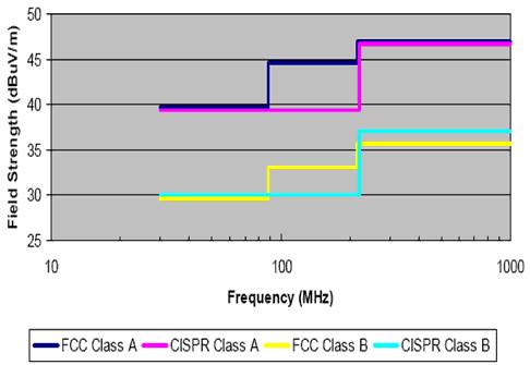
Figure 2 FCC and CISPR radiation limits - 30MHz to 1GHz, measuring distance 10m
In Figure 2, Class A limits electronic devices used in commercial, industrial, or enterprise environments. Class B limits are for home electronics. Class A restrictions may also apply to home electronics. Class B restrictions are more stringent because such devices may be placed close to the TV and radio receiving equipment.
Adapter Ring,Ring Camera Adapter,Lens Adapter,Camera Adapter
Shaoxing Shangyu Kenuo Photographic Equipment Factory , https://www.kernelphoto.com