0 INTRODUCTION Car safety is primarily concerned with how to maintain the safety of cars and people when the driver encounters changing traffic conditions while driving. At present, the advanced cruise-assisted expressway system (AHS) has been developed, which enables the vehicle to automatically interact with the signs on the lane, surrounding vehicles or intelligent transportation facilities through monitoring communication equipment installed on both sides of the road. However, in areas with poor road conditions such as winding mountainous roads and remote areas, these monitoring and communication devices cannot be installed everywhere. Even if these devices are installed in some sections, it is very difficult to maintain and protect their reliability and safety. It also consumes a lot of manpower and financial resources. Moreover, by analyzing the working principle of the AHS system, it is found that the AHS system cannot obtain real-time information of the vehicle operation, such as: the position of the car, the speed of the car, the braking torque, etc., and it is impossible to carry the two vehicles in the two workshops where the accident will occur. Workshop communication of important information such as speed. Therefore, the AHS system can only detect the occurrence of traffic accidents, and can not effectively take the initiative to prevent traffic accidents.
The system described in this paper does not require monitoring communication equipment installed on both sides of the road, so that it can transmit the driving information of the vehicles close to each other while the vehicle is running, and can take proactive precautions under appropriate circumstances. A potentially dangerous situation that effectively prevents traffic accidents. Therefore, the system can be regarded as a part of the development of future ITS technology, with significant practical value and theoretical significance.
This article refers to the address: http://
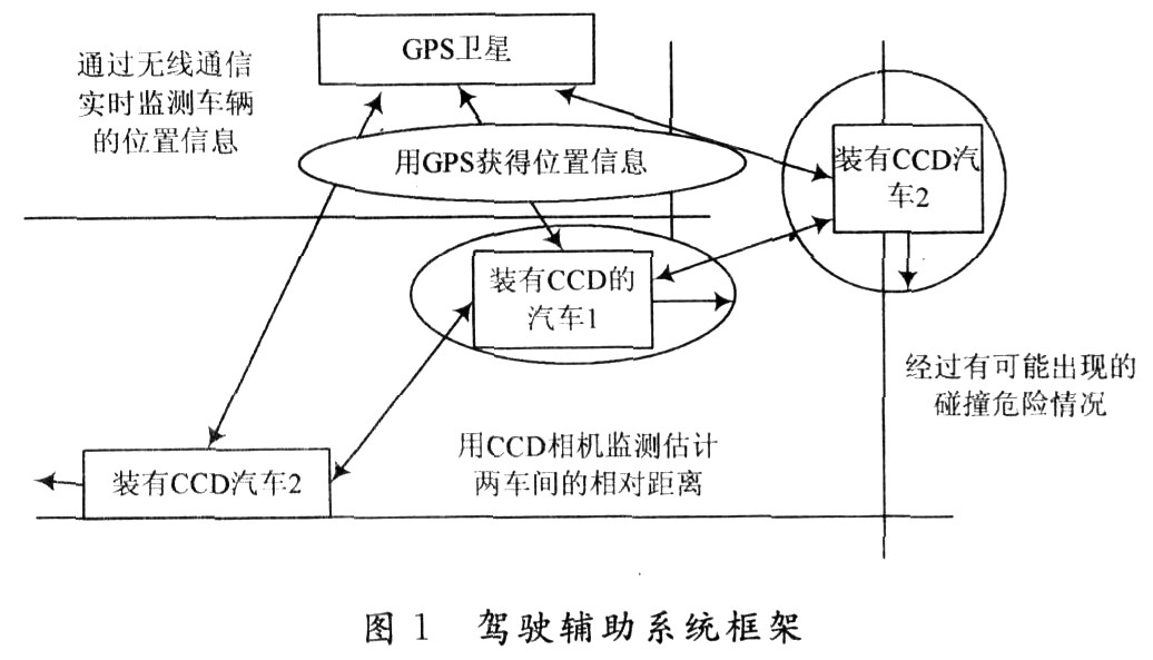
l Driving assistance system composition Figure 1 shows the schematic diagram of the ITS-based driving assistance system. It is mainly composed of GPS and CCD camera detection module, communication module and control module. Among them, the GPS and CCD camera detection module receives the GPS satellite signal through the GPS receiver, obtains the latitude and longitude coordinates, speed, time and other information of the vehicle, and uses the CCD camera installed at the front and the rear of the car to observe the situation on both sides of the road in real time. The communication module can transmit the detected related information and transmit the driving information in real time between cars that are close to each other; the control module can actively control when an accident occurs, thereby avoiding an accident.
1.1 GPS module and CCD camera detection module In the driving process of the car, the most likely place for collision accidents is at the corner. This is because during the design of the car, the front window has a dead angle of view, so that the driver does not turn when cornering. A good view, so that you can not make a quick and clear judgment on the upcoming accident. In order to minimize the problem of blind angle of view, the driver assistance system uses the GPS and CCD camera detection module to obtain the driving data of the vehicle, including the position and speed of the vehicle, the approach speed of the two vehicles, and the like.
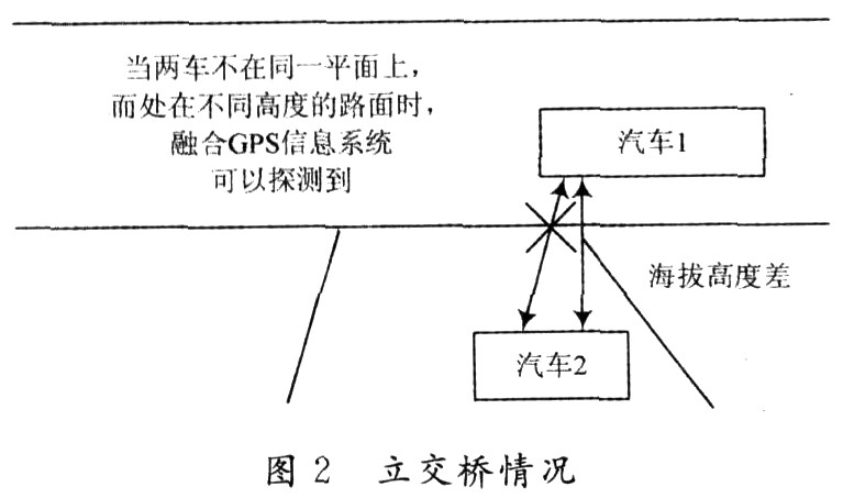
In order to reflect the distance information of the workshop, the road information in the geographic information system (GIS) is integrated into the GPS positioning data system to form a fused GPS information system. In GIS, in order to truly reflect the geographic entity, the recorded data not only contains the location, shape, size and attributes of the entity, but also records the interrelationship between the entities, so that the combination can well meet the needs of the system. Therefore, the position information transmitted by the GPS satellite includes not only the longitude and latitude of the car, but also the altitude and the positional relationship between the vehicles, so that the geographical position of the car can be more accurately indicated, and the information transmission between the two workshops can be avoided. The appearance of "overpass conditions" (Figure 2) will not cause the car to make a wrong judgment, resulting in unnecessary conditions.
The CCD camera installed at the front and rear of the car is the “blind zone detectorâ€, which is used to observe the conditions on both sides of the road in real time. Among them, the front CCD can detect the road condition after turning at the corner, and judge whether there is a vehicle approaching; the rear CCD can see the driving situation of the rear vehicle, and determine whether the vehicle affects the turning and overtaking of the vehicle.
Figure 3 shows a block diagram of the process of using GPS and CCD cameras to determine the occurrence of a hazard and to make a judgment based on the hazard. First, it is judged whether or not a vehicle approaches the vehicle, and the most dangerous approaching vehicle is used as a communication target. Secondly, the traveling information of the vehicle and the target vehicle, including speed, position, braking torque, and the like, are obtained through Ad Hoc wireless network communication. Based on this information, it is judged whether or not the driving condition of the target vehicle is normal. When the monitored information indicates that the target vehicle is not operating normally, the two workshops transmit important information such as braking torque to each other, and obtain the distance information of the two workshops in real time through the CCD camera according to the specific situation. In a specific case, the two vehicles MCU The controller will take active or automatic braking to avoid collision between the two cars, and the driver can also see this information through the monitor screen inside the car. Even in the event of different dangerous situations during driving, the driver assistance system is able to make correct and precise operations for different driving situations based on information obtained from GPS and CCD cameras. 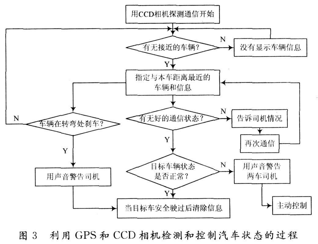
1.2 Communication Module The mobile Ad Hoc network is formed by the interaction of wireless terminals loaded on the car, without the need for other wired and wireless network support. Among them, each car is a mobile node in the mobile Ad Hoc network, and can freely join or leave the network. There is no network infrastructure in the mobile Ad Hoc network (such as the base station in the cellular network). All mobile nodes operate in a distributed manner and have a routing function. The mobile node itself can discover and maintain the routes of other nodes by using certain protocols. In addition to the data transmission suitable for this driver assistance system, there are some advantages that cellular mobile networks do not have:
(1) The network can be established at any time and used without other communication facilities, which greatly saves operating costs;
(2) It is not limited by the fixed topology, and has strong fault tolerance and robustness. In some extreme cases, the network can still operate normally even if some of the detected cars fail.
The driving assistance system relies on the state information between the vehicles to communicate with each other and monitor the driving state, which can protect the safety of the driving, including adjusting the driving state and avoiding a vicious collision. At present, the existing system can warn the driver of the dangerous situation, but can not make preventive measures on their own, and the system makes up for this defect. There are two main types of information transmitted using the Ad Hoc network:
(1) Timing transmission of status information obtained by GPS and CCD cameras and some sensors inside the vehicle, such as the position of the vehicle, the traveling speed, the braking torque, and the like. According to the study, these status information should be transmitted at very high frequencies, with each vehicle in the network transmitting approximately 5 to 50 times per second.
(2) Warning information for dangerous situations. Unlike the information sent periodically, these warning messages may come from communication vehicles within the communication range, and the nodes are far away, so multi-hop transmission is required, so this information is only sent out when a dangerous situation occurs.
Therefore, the system using mobile Ad Hoc network can implement real-time dynamic acquisition of vehicle driving conditions, which has the characteristics of low construction cost, short cycle and low maintenance cost, and is suitable for the current situation of intelligent transportation development in China. However, the mobile Ad Hoc network topology and physical layer protocol design, the processing of collected information and its prediction of future road conditions have yet to be resolved.
1.3 Control module When the vehicle information transmitted through the Ad Hoc network enters the vehicle controller, the obtained data will be analyzed and processed. If the results of the analysis are safe, no action is taken; when the results of the analysis are warned, proactive precautions are taken, as shown in Figure 4.
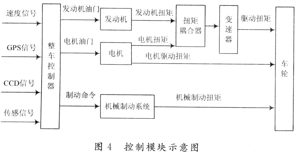
The vehicle controller is the core of the vehicle control. It judges the current state of the car according to the input signal, and determines the magnitude of the current control signal to each subsystem after a certain control logic and control algorithm. As shown in FIG. 4, the speed signal represents the current demand for the output driving torque of the entire vehicle. Similarly, the brake pedal signal indicates the demand for the braking torque of the entire vehicle. The vehicle control strategy studied in this paper uses a power-assisted control strategy. The engine MCU determines the required fuel supply amount and fuel injection timing based on the engine throttle signal from the assembly controller and the current engine speed, so that the EFI engine outputs torque to the torque coupler through effective tissue combustion. The motor drive system determines the drive torque output of the motor based on the input motor throttle signal characterizing the motor torque and the motor operating mode signal.
The vehicle controller calculates the required mechanical braking torque value according to the driver's brake pedal and the current vehicle speed to obtain the braking command of the mechanical braking system. Compared with the original vehicle, the wheel braking force comes from the friction braking. The brake system and the power transmission system that generates the feedback brake, the added feedback braking function is realized by the hybrid power and the transmission system. The feedback braking force comes from the braking torque of the motor and is applied to the driving wheel through the transmission system, and the feedback system The moving energy is transmitted back to the motor through the transmission system. This increases the reliability of the brakes, thereby increasing the reliability and safety of the driver assistance system.
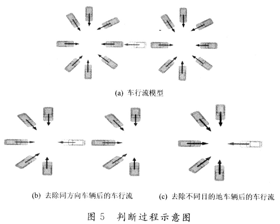
2 Vehicle positioning principle To make the driving assistance system operate safely and reliably, the transmission of important driving information between cars is the key. How to determine the car that communicates with the car is the basis. The judgment process is shown in Figure 5 and is divided into 4 steps.
(1) Assume that this is a vehicle flow model that travels from all directions (as shown in Figure 5(a));
(2) The target vehicle traveling in the same direction as the vehicle has no threat to the vehicle, so it is removed from the candidate (as shown in Figure 5(b));
(3) Vehicles with different driving destinations of the vehicle are also removed from the candidate (shown in Figure 5(c));
(4) The remaining vehicles are considered as communication candidates.
In the process of judging the direction of travel of the vehicle, the signal transmitted by the GPS is analyzed, and the direction of travel of the vehicle is determined by the position change of the vehicle; and in the interior of the vehicle, the gyro sensor is installed to directly detect the direction in which the vehicle is moving. When the directions of travel indicated by the two pieces of information are the same, the exclusion of the communication candidate vehicle is performed according to the above removal rule; when the directions of travel indicated by the two pieces of information are different, the vehicle is reserved as a communication candidate. The remaining candidate communication vehicles receive GPS satellite signals through the GPS receiver, and obtain information such as the latitude and longitude coordinates, speed, and time of the vehicle. From this information, it is possible to calculate the distance between the vehicles, the speed of the approach between the vehicles, and the like, and to communicate the vehicle closest to and closest to the fastest speed.
In order to improve the positioning accuracy of the car, the system uses differential GPS technology. When the car travels to underground tunnels, high-rise buildings, highways, etc. and does not capture GPS satellite signals, the system can automatically import the autonomous navigation system. At this time, the speed of the car is detected by the vehicle speed sensor, and the micro-processing unit is used. Data processing, directly calculating the distance of advancement and the distance and approach speed of the workshop from the speed and time. The car position coordinate data and the forward direction measured by GPS satellite navigation and self-discipline navigation have certain errors with the actual travel route trajectory. In order to correct the error between the two, the GIS system is integrated into the GIS system, and map matching technology is added. The matching circuit automatically corrects the error between the route of the car and the road on the electronic map, and the map matching circuit is quickly processed by the finishing process of the micro processing unit to obtain the correctness of the car on the electronic map. Location to indicate the correct driving route.
3 Conclusion Driving assistance system, through the obtained GPS and CCD camera signals, monitor the status information of the vehicle during the real-time operation, and predict the potential collision accidents in real time, when the judgment result indicates that a collision accident will occur. Through the Ad Hoc network, wireless communication between vehicles is carried out, and the driving parameters of the vehicle and the driving parameters of the communication vehicle are transmitted to each other and transmitted to the microcontroller in the vehicle, so that the microcontroller issues an operation instruction to remind the driver to do Out of control, when the situation is particularly urgent, the vehicle can be properly controlled. Since the driver assistance system does not require fixed monitoring equipment installed on both sides of the road, the system is very effective for future ITS.
220Uh Inductor,High Current Inductor,Magnetic Inductor,Toroidal Core Inductor
IHUA INDUSTRIES CO.,LTD. , https://www.ihuagroup.com