With the development of automotive electronics in the direction of intelligence, standardization and networking, the proportion of software development in product development is increasing. Adopting platform-based design methods to reduce costs, shorten development time, and make full use of existing resources has become a kind of The inevitable trend.
This article refers to the address: http://
Currently, the main automotive electronic software development standards are AUTOSAR, MISRA and OSEK. Zhejiang University CCNT Laboratory has developed SMARTCAR automotive electronic software platform based on existing standards and platforms, including smart car platform and automotive electronic software development platform. 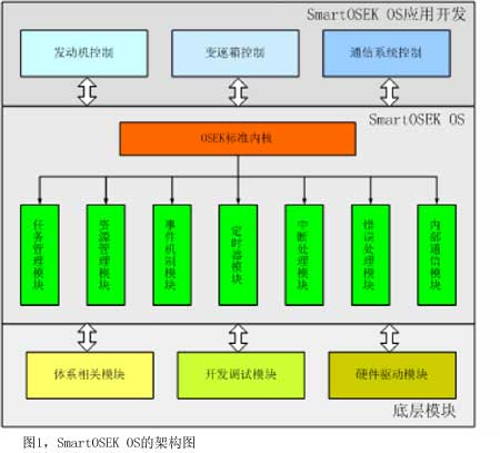
Wu Zhaohui, the vice president of Zhejiang University, is also the academic leader of CCNT. He said that ScudWare, an adaptive middleware platform for smart cars, and a smart car space prototype system developed on the basis of this are the in-vehicle processing centers. A computing environment consisting of a context collection device and a series of remote web servers. The main purpose is to automatically provide appropriate services according to user settings or current environmental characteristics, reducing the number of times users initiate service requests, forming spontaneous in the car. Customized service space provides users with a safe and comfortable driving environment. The automotive electronic software development platform SmartOSEK mainly includes the high-reliability and real-time embedded operating system kernel SmartOSEK OS, the board-level support architecture SmartOSEK BSS and the model-based graphical development environment SmartOSEK IDE. Focus on solving the problem of operating system requirements for complex automotive electronics applications, modeling description problems for automotive fields, validation of vehicle control software validation, automatic generation of documents and code during development, and model-based software development ideas Change the traditional development method of embedded systems, and ultimately improve the efficiency and product quality of automotive electronic control system product development, and reduce development costs.
The structure of SmartOSEK
The SmartOSEK standard focuses on OSEK OS, OSEK OIL, OSEK COM, and OSEK NM standards. The AUTOSAR standard, currently, draws on its Architecture Communication, RTE, System Services, Peripherals standards, and related parts of MethodologyAndTools and Application InteRFaces. The MISRA standard mainly draws on its 127 rules for automotive electronic security codes.
Embedded real-time operating system SmartOSEK OS
SmartOSEK consists of three parts: operating system, board level support and development tools. Its operating system part SmartOSEK OS is implemented strictly according to OSEK/VDX specification, and it is the first embedded in the OSEK specification certified by OSEK official organization in China. Real-time operating system.
SmartOSEK OS strictly implements the kernel modules specified by the OSEK standard, including task management module, resource management module, event mechanism module, timer module, interrupt processing module, error handling module, and internal communication module.
The SmartOSEK kernel module requires the support of the underlying modules, including system-related modules, development debug modules, and hardware driver modules. The system-related module implements closely related parts of the system, such as context switching; the development and debugging module implements monitoring, tracking and debugging of the application for a specific platform; the hardware driver module includes drivers for each research peripheral. The application development of SmartOSEK OS is mainly for automotive electronic control systems, including engine control, transmission control, and communication system control. Figure 1 is an architectural diagram of the SmartOSEK OS.
SmartOSEK OS can meet strict on-chip memory requirements, the kernel is between 4KB and 12KB (32-bit PowerPC platform); the context switching time of SmartOSEK OS on MPC555 with 40M frequency is microsecond; the maximum interrupt masking time is 21.72 Ss; can withstand up to 40kHz interrupts.
Board level support SmartOSEK BSS
Board Level Support SmartOSEK BSS is an open, versatile platform that shields specific hardware details and provides services to the upper layer operating system and applications through the API, making the operating system and applications independent of the hardware. For the new hardware platform, as long as SmartOSEK BSS can be implemented, the upper layer software can be easily transplanted. At the same time, SmartOSEK BSS should also be able to be used on different development platforms, although its implementation may be different, but the interface is unified.
Referring to the division of the software system in the AUTOSAR standard, the board-level support platform adopts a hierarchical structure design, which is divided into a microcontroller abstraction layer and an ECU abstraction layer, and the entire board-level support platform is divided into four modules according to functions.
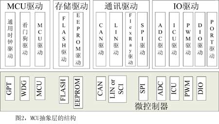
The MCU abstraction layer contains various drivers and is divided into four parts according to their functional characteristics: IO driver, communication driver, memory driver and microcontroller driver. They are software modules that provide direct access to peripherals within the microcontroller or to external devices that are memory mapped to the microcontroller. The structure of the MCU abstraction layer is shown in Figure 2.
The ECU abstraction layer contains drivers for external devices that are connected to the microcontroller via a network. The ECU abstraction layer is also divided into four parts: IO hardware abstraction, communication hardware abstraction, storage hardware abstraction, and on-board device abstraction.
Integrated development environment SmartOSEK IDE
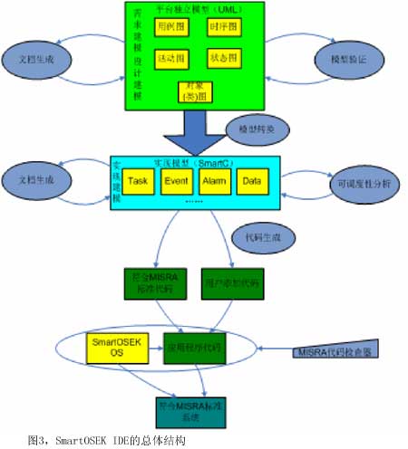
The SmartOSEK IDE is an integrated development environment for automotive electronics applications that supports the SmartOSEK operating system. It draws on the model-driven design idea and provides UML requirements modeling, SmartC algorithm modeling, statechart model validation, system schedulability analysis, automatic code generation, and automatic documentation around the V-shaped process in automotive electronic software development. Generate a complete set of development toolchains. The overall structure of the SmartOSEK IDE is shown in Figure 3.
According to the model-driven development process, the first is UML requirements modeling and structural modeling, and UML model validation to determine whether the design meets the requirements. The SmartOSEK IDE provides a model conversion tool that directly converts the UML model into a SmartC model and performs specific algorithm modeling on the SmartC model. After the model is built, the model can be analyzed for schedulability to ensure that the model meets the schedulability requirements. Finally, high-quality C code and word format documents conforming to the MISRA standard for the target platform can be automatically generated.
SmartC is a system description language developed by the Embedded System Engineering Center (ESE) of Zhejiang University CCNT Laboratory for automotive electronics. It complements UML. The core of SmartC is its hierarchical modeling method. From top to bottom, the system design is divided into five levels: system layer, component layer, task layer, sub-task layer and component layer. The system layer focuses on the structure and requirements of the whole system. The component layer focuses on the system's functional requirements and software deployment. The task level focuses on the system implementation, and the component layer focuses on the implementation of the control algorithm.
SmartOSEK IDE supports automatic generation of application C code for SmartOSEK OS from models. The generated C code can be compiled and run directly with the SmartOSEK OS and does not need to be manually modified. The SmartOSEK IDE provides a MISRA-compliant code checker for code that users manually write in the model.
Auto-generation technology is an important means to improve the efficiency of software development. SmartOSEK IDE automatic generation tools include automatic generation of program code and automatic generation of design documents. Automatic generation of program code According to the design of the system model and the configuration file of the system, the pre-made program code is quickly combined into an actual application system, and the system framework can be automatically completed. The pre-made code includes various multiplexed components, various drivers, and operating system code. The richer the pre-coded code, the more efficient the code is automatically generated. The automatic generation of design documents refers to the automatic generation of relevant design documents based on the designed system model. Automated generation technology eliminates barriers between stages of traditional software development methods, reducing problems and increasing efficiency. Another great advantage of the automatic generation technology is that it keeps the generation source and the generation target synchronized, that is, the model and code can be updated synchronously, which is very good to maintain the consistency of the system.
For different hardware platforms, SmartOSEK IDE provides configuration tools to configure and select before automatically generating code. After configuration, it can automatically generate code that adapts to run on different platforms. The automatically generated code framework is pre-fabricated for different platforms in advance and has been optimized accordingly.
Any QI enabled device like iPhone X/ 8/8Plus, Galaxy, Samsung S7,S7 Edge, S6,S6 Edge, Nexus 4/5/6 (NOTE: Other device have no wireless charging function except putting on extra receivers.)
Starts the moment you place down any Qi-enabled device or device equipped with a Qi-compatible cover. No cables or USB interface required. Input: AT LEAST 5V/2A; Output: 5V/1A
Wireless Charger,Universal Wireless Charger,Portable Wireless Charger,Mobile Wireless Charger
Shenzhen Waweis Technology Co., Ltd. , https://www.waweispowerasdapter.com