This article introduces the hardware composition, software design, communication principles and communication commands of the computer monitoring system of the inverter from the perspective of computer monitoring and control of the inverter, and Emerson inverters, which are currently widely used. The system has been verified by field tests in actual projects.
1 Monitoring system hardware structure In the overall structure design of the monitoring system hardware, the host computer serves as the main control unit. In order to enable communication between the computer and the inverter, a conversion interface should be installed between the two, so that the computer passes the RS232 / RS485 conversion interface Connected to the EV3000 inverter, the inverter motor is controlled by the inverter drive, and the inverter motor drives the turntable to rotate. The encoder feeds the motor rotation information back to the inverter, so that the host computer sends a communication command to control the inverter. The inverter drives the motor to make the turntable act in response to the command. The encoder transmits the feedback information to the inverter to complete the control process. The hardware structure of the monitoring system is shown in Figure 1.
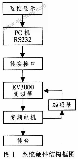
According to the actual working environment, the upper PC in this system selects Advantech industrial control computer, adopts EV3000 frequency converter as the core control device of the monitoring system, and the use of frequency converter can strengthen the protection function of the system to realize overvoltage, overcurrent, undervoltage, open circuit and short circuit And other protection functions; realize stepless speed regulation, wide speed regulation range, good characteristic curve, high control accuracy and good energy saving effect; frequency conversion motor adopts YVP series frequency conversion speed regulation three-phase asynchronous motor produced by Jiaxing Juneng Motor Factory. Wide speed range, low vibration, low noise, can be matched with various SPWM frequency conversion devices. Constitute AC variable frequency stepless speed regulation system.
2 Communication method of monitoring system In order to realize the communication between PC and inverter, we must first understand the communication protocol between them. Hexadecimal numbers are used between the computer and the inverter, and the data is automatically transmitted between the computer and the inverter using ASCII codes. The background of the PC is the master, and the inverter is the slave. Adopt the communication method of "polling" by master and "answering" by slave.
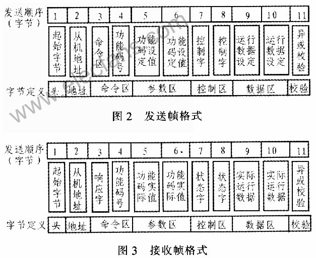
The data frame structure is: frame header, user data, frame end. Frame header: including start byte, slave address; frame end: check data (exclusive OR check); user data: including parameter data and process data; parameter data: including function code operation command, response, function code number 3. Function code setting / actual value, there is no parameter data in short frame; process data: including master control command / slave status response, master running master setting / slave running actual value.
EV3000 can communicate through long and short frames. The short frame is used to independently transmit the control word and status word required by the automatic control system; the long frame includes both the control word and the status word and contains content related to operation control, observation, maintenance, and diagnosis (the content is subject to the inverter itself Functional limitations). This article uses long frames as an example. The frame format for communication from the computer (controller) to the inverter is shown in Figure 2. The frame format for communication from the inverter to the computer (controller) is shown in Figure 3.
The parameter calibration instructions of EV3000 are as follows:
1) The frequency is scaled to 1: 100. To operate the inverter at 50 Hz, the main setting should be 1388H (5 000).
2) The scale of time is 1:10. If the acceleration time of the inverter is 30 s, the function code should be set to 012CH (300).
3) The scale of the current is 1:10. If the inverter feedback current is 012CH, the current of the inverter is 30 A.
3 Monitoring system software design The software design is based on the Windows platform visual integrated development tool Delohi software, using the Spcomm control provided by Delphi's third party, can easily and conveniently realize the serial communication of the application. The main attribute methods of Spcomm include: 1) CommName: set serial port; 2) BaudRate: set baud rate; 3) Paritv: parity bit; 4) ByteSize: set byte length; 5) StopBits: stop bit; 6 ) The Startcomm method is used to open the serial port; 7) The StopComm method is used to close the serial port; 8) The WriteCommData method is used to send a string to the write process. The monitoring interface is shown in Figure 4.
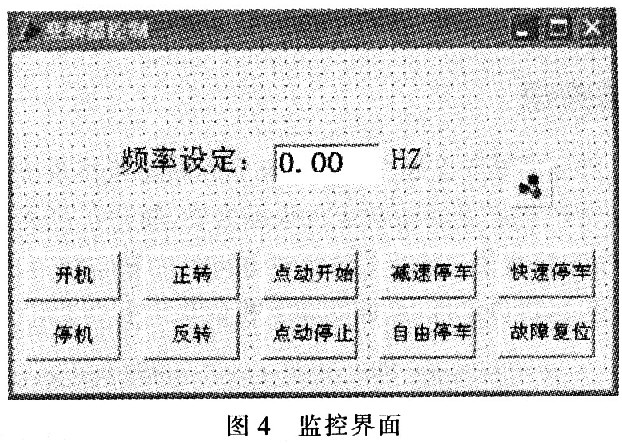
The monitoring program interface is mainly used for interaction between the user and the frequency conversion speed regulation system. Through this interface, on the one hand, the user can conveniently control the action of the motor, on the other hand, it can also monitor some of the more important parameters of the frequency converter in real time, such as current, frequency, torque and speed of the motor, etc., and observe its running status Is it normal. The serial port must be initialized before the computer communicates, and the parameters must be the same as those of the inverter, otherwise it cannot communicate. Inverter communication program flow is shown in Figure 5.
 In actual application, the corresponding frequency is set by the computer control software to make the turntable run under the matched acceleration. Table 1 lists the correspondence between the inverter frequency f, turntable normal acceleration G, turntable angular velocity ω, and turntable speed N.

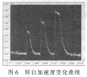
Fig. 6 is the frequency-controlled motor-driven turntable according to the three frequency conversion actions in Table 1, and the progressive acceleration of the turntable rotates at 40, 60, and 80 g in steps. By analyzing the experimental data, it can be seen that the host computer monitoring software can control the movement of the variable frequency motor stably and accurately, and complete the operation process.
4 Conclusion The experiment proves that based on Emerson's EV3000 variable frequency speed regulation monitoring system, the normal driving and running status of the motor are successfully monitored, the control logic system is simplified, and the operation is simple and convenient. The real-time monitoring of the motor by the host computer greatly improves the running stability of the motor, thereby achieving stable and safe operation of the motor.
STP series plating rectifier power supply is an economical rectifier power supply made with high-frequency switching technology based on IGBT switching devices. It is an industrial power supply product developed by our company for electroplating, electrolysis, water treatment, hard oxidation and other industrial applications.

This series of electroplating power supplies are featured for complete control functions, stable performance, and competitive cost performance. Compared with the thyristor-based SCR plating rectifier power supply, the switching mode plating rectifier power supply has much higher efficiency. Under the same output power, up to 20% ~ 30% power loss can be reduced for the customers. This series of electroplating power supplies can reach ultra-high DC output of up to 2000KW with Max. current at 50000A.
The surface treatment industry does not have high requirements for plating DC power supply ripple, and most of models required for plating application are low-voltage and high-current output. The electroplating rectified power supply product removes the unnecessary LC circuit components at the input and output ends, and is targeted at the stability of the output current and the long-term operation capability of the high-frequency rectified power supply to meet the needs of the surface treatment process. In order to overcome the application's harsh environment and long-term high current working conditions, the power supply basically adopts the water-cooling method, and the internal components of the power supply are treated with three preventions, which can realize the effective heat dissipation of the power supply and the effective protection of the internal components of the power supply to improve the reliability of the rectifier power supplies.
Electroplating Rectifiers, Plating Rectifier Power Supplies, Electroplating Rectifier Power Supplies, DC Plating Rectifiers, Plating Power Supplies
Yangzhou IdealTek Electronics Co., Ltd. , https://www.idealtekpower.com