Fifteen years ago, the most common way to connect to the Internet was to send data over an analog telephone voice channel over an analog telephone voice channel. This technology uses existing standard twisted-pair telephone lines that have already been deployed, without any changes to the "last mile" technology, so it is very cheap for users and quickly dominates the entire communications market. This method is very attractive without having to dig the road and not change the central office room (CO).
The analog modem has a peak speed of 56Kbps. Why is 56Kbps? Why are you no longer taller? Simply put: this is not a "theoretical" possibility, but this theoretical limit limits the development stage of ADSL technology.
Analog modems use existing voice channels that are rigorously regulated by the ITU-T committee. The channel has a defined bandwidth (4 kHz, including the guard band) and is hardware filtered in the central office before entering the Muldex (Multiplexer Demultiplexer). Muldex is a device connected to the phone in the central office.
What is the maximum data rate that can be transmitted over a 4 kHz analog channel? The key to this problem is to understand ADSL.
The correct answer is: “Depends on the noise level of the channel.†Claude E Shannon gave us the answer as early as 1948, as long as the noise is low enough, it can be transmitted at any bit rate, which sometimes surprises us. . In fact, Claude E Shannon more accurately associates the maximum bit rate quantitatively with a given channel bandwidth and noise level. You can use Shannon's famous formula:
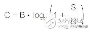
Shannon's well-known formula
Where: C: maximum bit rate, unit: bit/s (capacity), B: bandwidth, unit: H, S/N: channel signal to noise ratio.
The ITU-T specifies the bandwidth and noise level of the voice channel, defining the actual maximum bit rate of the twisted pair telephone line - 56 Kbps, very close to the channel capacity.
Instead of using a standard voice channel, ADSL uses another channel to break the Shannon limit of the voice channel.
In the telephone system, each user is connected to the central computer room via twisted pair. The twisted pair is used for a short time and is only used when making a call. It only occupies the channel bandwidth below 4 kHz, which is higher than 4 kHz. The bandwidth is obviously not used. ADSL uses unused bandwidth and reserves channel bandwidth below 4 kHz as a standard voice channel. Users can exchange data while making a telephone voice call.
How wide is the ADSL channel and how big is the noise? This is not standardized, which is why each ADSL modem measures line noise at startup and then establishes the optimal bit rate based on the user channel conditions.
The speed at which each user connects to the central office depends on the channel itself. The user can read the line rate on the control panel of the home ADSL modem.
ADSL is indeed a very good idea. It makes better use of lines that are already buried underground, without having to make any changes to the last mile, and the old phone can be compatible with new technology. The user only needs to connect a filter (ie "separator") at home to separate the telephone voice bandwidth from the ADSL bandwidth. In short, this approach is simple and inexpensive.
Each line in the central office room is also equipped with a similar filter. The filter connects the voice channel to Mulder and connects the high-bandwidth portion of the line to a new device called Digital Subscriber Line Access Multitasking (DSLAM) that processes only data. Telecom operators only need to establish a DSLAM near each Muldex location in each central office to provide ADSL services to customers.
The DSLAM is a pure data communication device with an analog front end (Digital Front End). It collects all ADSL data from a wide range of user groups. All data is typically sent to a Field Programmable Gate Array (FPGA) where it is processed and aggregated into an Ethernet link.
High-speed Ethernet links are typically connected to the Internet or transmitted over Synchronous Digital Hierarchy (SDH) or Optical Transport Network (OTN). The ADSL standard has been evolving, and the back-end connection of the DSLAM used to connect to the Internet can be varied depending on the network configuration: Ethernet, XAUI, SDH, and OTN.
These are ideal conditions for using FPGAs because of the ability to create fully programmable back-end connections and the use of programmable components to meet the evolving ADSL standard requirements. The ADSL architecture looks so good, especially if you can upgrade your phone network naturally, it's hard to imagine what people want... But ADSL has limitations, which is why the market is moving toward Passive Optical Network (PON) technology.
The limitations of ADSL are still determined by Shannon's theory. It is difficult to make the ADSL rate exceed 15 Mbps using twisted pair. This is not a limitation of ADSL technology itself, but a limitation from the average distance between the user and the central computer room. If you want to be faster, we must change the “last mile†and minimize the change of the last mile. The cost required. Of course, we can provide SDH (with Ethernet) to each customer to meet these needs, but this method is too expensive. PON is the best answer to this problem because it provides the best balance between upgrade cost, performance, and last-minute minimum rework costs.
How PON worksThe service provider passes a fiber to a "roadside" a few hundred meters from the customer's radius. Instead of providing one fiber for each user, one fiber is used instead of dozens of twisted pairs. Each user is provided with fiber through the PON splitter, and the user can only access his own part of the multicast material from the central office and is limited by the encryption algorithm.
In the upstream direction (shown in Figure 1), the fiber from each user is connected to the passive splitter and multitasking to a single fiber that connects to the central office. The equipment responsible for receiving data from the optical fiber in the central office is called an Optical Line Termination (OLT). This architecture is completely different from ADSL. The advantage of PON is that the junction box on the street is optical and still passive. There are no active components in the box. This is a key advantage of PON technology: it can help suppliers reduce maintenance costs. To the lowest.
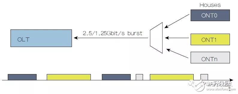
Figure 1 PON upstream direction
The disadvantage of this approach is that the service provider must replace the original twisted pair with a limited number of fibers. In order to reduce the cost of transplantation, PON has to be built in the form of hybrid technology at the expense of performance. The user connects to the junction box on the street via ADSL, but through the optical connection from the street to the OLT.
With this hybrid solution, the speed of ADSL is much faster, because the DSLAM is only a few hundred meters away from the user, not in the central office. The downside is that the hybrid junction box on the street is now active because it requires a small DSLAM to be loaded.
PON embodies the balance between cost and performance. This is not the best technical solution like the old 56Kbps modem, but it will continue to expand in the future.
The OLT has another key technology part: the front end. In the upstream direction, all users are connected to the same receiver through a passive fiber splitter. Therefore, the user must perform burst transmission, one batch at a time, because the user shares the fiber of one OLT. All burst transfers operate at the same frequency but with user independent phase. The OLT receiver resynchronizes its sampling phase at the beginning of each burst transmission to properly receive the data.
Each burst has a specific mode at the beginning of the preamble position, which indicates that the OLT locks each burst transmission. The front end receiver of the OLT is called the "Burst Mode Frequency and Data Recovery (BCDR)" unit.
Increasing the preamble time makes it easier to design the BCDR, but a longer preamble obviously reduces the efficiency of the upstream bandwidth. The BCDR is a key OLT component. Its efficiency directly affects the uplink efficiency of the PON line, which in turn affects the revenue per bit of the PON operator.
Xilinx's FPGA technology is common in OLTs, not only for the back end, but also for the front end, as in the DSLAM. Xilinx offers a comprehensive BCDR solution through the UltraScale All Programmable component family. Specifically, the BCDR uses 32 bits to determine the lock time for efficient uplink communication. This feature goes beyond the ITUTG984, G987 and G989 specifications. The BCDR is equipped with instructions and accessories to support the user in solving the following problems:
How to simulate BCDR? How to verify BCDR?For integrators, the first issue is to choose a product. The BCDR can only be tested in a PON environment, which is the product of the integrator. It is not possible to develop the product first and then verify the BCDR. What happens if we find that the BCDR does not meet expectations at the end of the development cycle?
This is why Xilinx has introduced a BCDR-based framework. Together with the BCDR, you get a complete analog test platform with a data packet generator and a data packet checker to prove the correct operation of the BCDR.
In addition, the development environment not only tests the BCDR; it also puts pressure on it; discovering its ultimate performance. Here are some examples:
Generate multiple ONUs.
The ONU can be forced to run in "hammer" mode, ie the data packet to data packet phase transition is always 0.5% of the UI. We want to make sure that the BCDR is completely immune to this fluctuation.
Each time a multi-frame data packet is restarted, all data packets generated in hammer mode are moved by 1 picosecond to ensure that the BCDR phase detector has no "dead" zone. The lock time must always be 32 bits - short and ok.
It is also possible to change the preamble length of the data packet between 0 and 8000+, so that it can meet the most stringent ITU.T PON requirements and relatively loose IEEE PON requirements.
Figure 2 shows the simulated environment architecture provided with the BCDR in XAPP1277. The simulation environment runs through a script and can see the waveform in a few minutes without writing code.
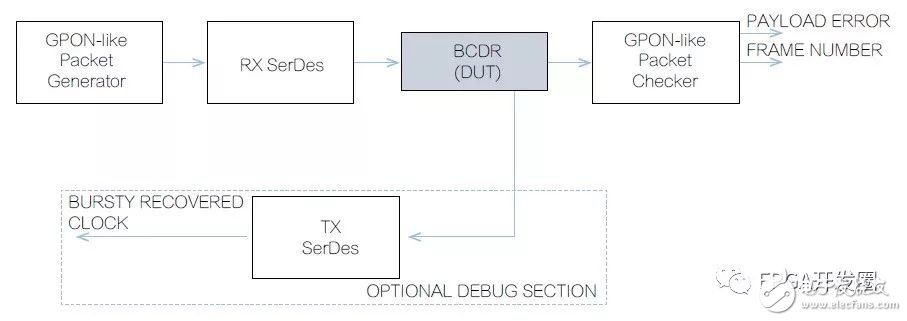
Figure 2 Simulation environment provided by the BCDR
The software stress testing framework is a great starting point for hardware vendors. However, you may need to see the hardware work, which is the work of the second BCDR framework; the framework uses the KCU1250 characterization suite for Kintex UltraScale FPGAs, and continuously generates and examines data packets in hardware to avoid seeing a single Bit error or loss of a single data packet.
How to use a demo card to simulate a PON environment? How to test the hammer mode with 1 BCDR?Upstream data is always synthesized at double rate, and the TX serializer always generates two identical bits per upstream bit. Thus, at the architectural level, the hardware framework can simulate a 0.5UI transition between any two consecutive data packets - the worst case that can occur in a PON environment. The hardware framework puts pressure on the BCDR by inserting the worst phase step between any two data packets.
The payload in the framework is a truncated PRBS that restarts after the delimiter of each data packet. If the BCDR skips the data packet, you will see a load error; you can also change the preamble length on the fly. The entire hardware testbench supports scripting and embeds the Vivado hardware analyzer with a set of controls.
In addition to hammer mode testing, error insertion and accumulation, many serial/deserializer (SerDes) features and many features of the BCDR itself, such as digital bandwidth, can be changed during operation. For users who are not familiar with FPGA technology, SerDes configuration is another part that will confuse them. Therefore, the BCDR framework provides instructions for step-by-step instructions on how to configure SerDes to help users set up the PONOLT interface. Figure 3 is a schematic diagram of the GT (Gigabit Transceiver) GUI showing how the framework guides configuration and how to avoid hardware complexity.
These technologies allow users to select complex products such as BCDRs through a GUI. In principle, you can do this without knowing the basics of the technical details. Once the BCDR is evaluated, the hardware testbench becomes the best starting point for launching a real project. Simply delete the demo datagram generator/checker and replace these modules with real PON MACs to embed the BCDR.
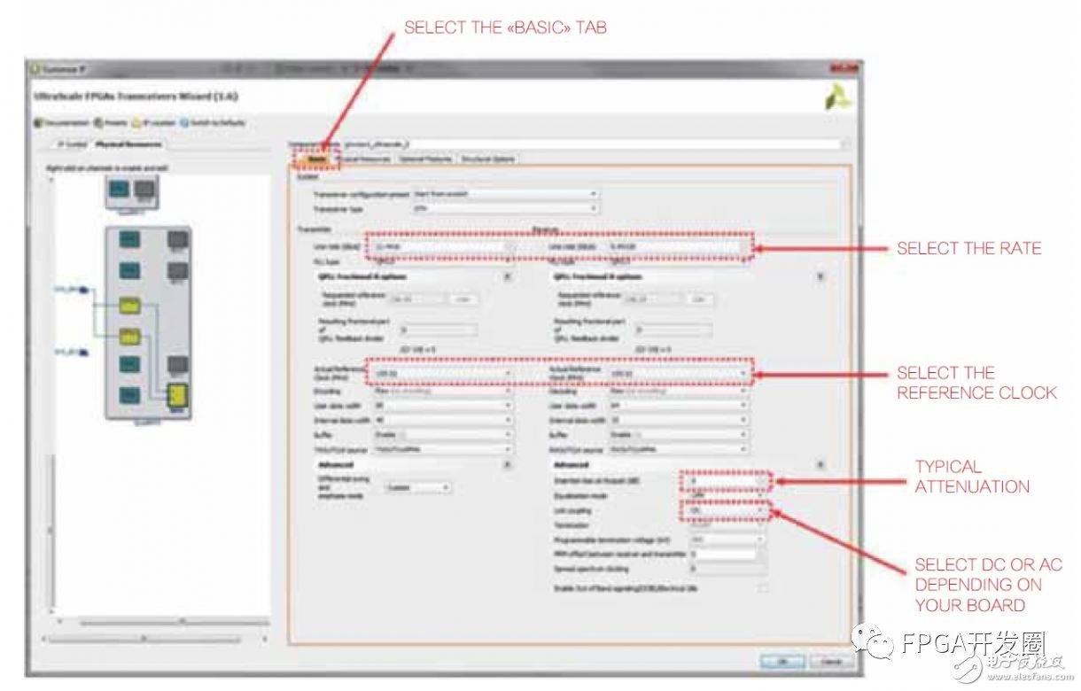
Figure 3 SerDes configuration for setting up a multi-rate OLT interface
Led Floor Panels,Led Dance Floor Panel,48W Led Light Panel,Floor White Uplight Panel Led
Kindwin Technology (H.K.) Limited , https://www.szktlled.com