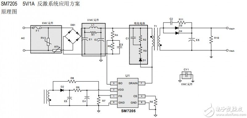
The primary-side feedback control ICSM7205 of switching power supply with high performance and low standby power consumption replaces Xinpengwei Power switch, integrates the MOS high voltage power 730V, constant voltage high accuracy over the full range of the output voltage input, precision of less than ± 5%, the standby power consumption of less than 30mW @ 230Vac, no loop compensation, the system can save the light Coupling components such as TL431 to reduce costs, and provides quasi-resonance and frequency jittering functions to improve the EMI characteristics of the system, while meeting the sixth-level energy efficiency. The chip integrates cycle-by-cycle peak current limit, overcurrent protection, VDD undervoltage protection, VDD overvoltage protection and other functions to improve the reliability of the system.
Primary-side feedback control ICSM7205 standby power consumption
No loop compensation required
Built-in programmable line network voltage detection function
Built-in leading edge blanking circuit (LEB)
Built-in quasi-resonance
Built-in ±7% frequency jitter
Built-in 730V high voltage power MOS
Meet the sixth level of energy efficiency
With overcurrent protection, overload protection
VDD overvoltage protection and other protections
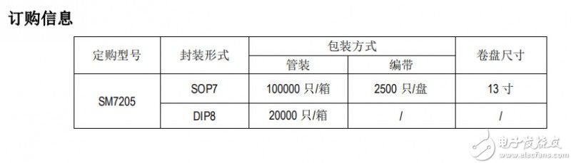
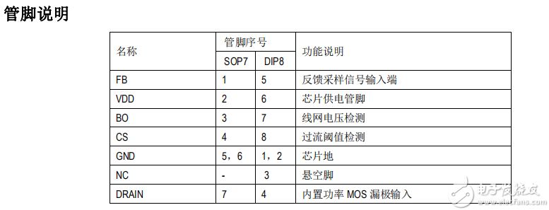
Package form: SOP7, DIP8
Primary side feedback control ICSM7205 application field
DVD, DVB, adapter
Printer power
Chargers and adapters for mobile phones/cordless phones, PAD, digital cameras, MP3 and other products
Low-power power adapter
Auxiliary power supply or standby power supply for computers, TVs and other products
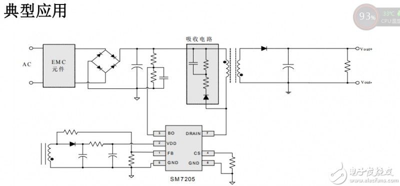
Primary side feedback control ICSM7205 function description
SM7205 is a high-efficiency, ultra-low standby power consumption, a constant-voltage primary-side control switch with built-in high-voltage 730V power MOS. It uses variable frequency control to adjust the output voltage. The chip includes an oscillator, a feedback circuit, a frequency modulation, a current limiting circuit, and a leading-edge blanking logic control circuit of the constant voltage control.
Constant pressure working mode
The controller adjusts the feedback pin voltage through frequency conversion to maintain it at the level of VFB. After the high-voltage switch is turned off for 2.5us, the feedback pin voltage is sampled. At light loads, the current limit is also decreased, thereby reducing the transformer magnetic flux density.
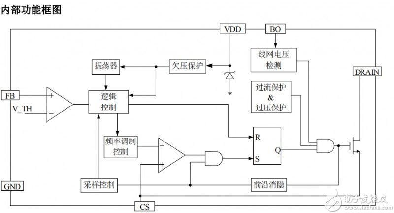
Primary-side feedback controls ICSM7205 auto-restart and open-loop protection. Once there is a failure, such as output short-circuit or open-loop, the SM7205 chip will enter the corresponding protection mode, as described below. If the voltage of the feedback pin drops below VFB during the flyback , the converter enters the auto-restart mode before the sampling delay time exceeds 50 ms, and the power MOS is disabled for 1 second . The auto-restart circuit alternately enables and closes the power MOSFET until the fault is eliminated.
Primary-side feedback control ICSM7205 current limit point
The primary-side feedback controls the ICSM7205 current limiting circuit to detect the current of the power MOS. When the current exceeds the internal threshold (ILIMIT), the power MOS is turned off during the remainder of the cycle. After the power MOS is turned on, the leading edge blanking circuit will suppress the current limit comparator for a while (tLEB). Leading edge blanking time and current spikes produced by the capacitance and reverse recovery time of the rectifier tube caused premature turned off MOS.
Principle of Constant Pressure
The logic controller adjusts the feedback pin voltage to maintain it at the level of VFB. After the high-voltage switch is turned off for a period of time , the feedback pin voltage is sampled. At light loads, the current limit is also decreased, thereby reducing the magnetic flux density of the transformer.
The 5 and 6 pins of the primary-side feedback control ICSM7205 need to be laid with copper for heat dissipation (if it is a double-sided board, the top and bottom layers need to be laid with copper), grid or linear copper leakage can be used to reduce the temperature of the chip and improve the performance of the system. When wiring the DRAIN pin, the loop distance to the transformer should be as short as possible, the loop area should be small, and large-area copper paving cannot be used. The ground of the VDD capacitor should be close to the ground of the chip. The ground of the FB divider resistor should be close to the ground of the chip. The Y capacitor should be grounded at a single point (connect a wire directly from the input electrolytic capacitor). The primary and secondary safety distance must be greater than 6mm, and less than 6mm requires grooving.
Usb Speakers,Pc Speaker Usb,Mini Usb Speaker For Pc,Usb Mini Speaker
Comcn Electronics Limited , https://www.comencnspeaker.com