After VLANs are assigned, Layer 2 communication cannot be performed directly between different VLANs. If you want to achieve inter-VLAN communication, you can take one of the following three options.
1. Layer 3 VLANIF interface Solution
This is a solution for inter-VLAN communication through the third layer (network layer) in the computer network architecture. Each VLAN can be configured with a Layer 3 VLANIF logical interface. These VLANIF interfaces serve as the default gateways for the internal hosts of the corresponding VLAN. The IP routing function of the Layer 3 switch enables Layer 3 interworking of different VLANs on the same switch. Layer 3 interworking between different VLANs on different switches requires the route between the network segments where each VLANIF interface resides.
In addition to the S1700 series, all other Huawei S series switches are supported.
On the network shown in Figure 6-20, the Switch is divided into two VLANs: VLAN 2 and VLAN 3. Inter-VLAN communication can be implemented through the following configurations.
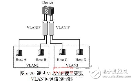
(1) Create two VLANIF interfaces on the device and configure the IP address of the VLANIF interface. The IP addresses corresponding to the two VLANIF interfaces cannot be in the same network segment.
(2) Set the default gateway of the user equipment in each VLAN to the IP address of the VLANIF interface of the VLAN to which it belongs.
The basic principle of inter-VLAN inter-VLAN communication through the VLANIF interface is described in the example where the host A in VLAN 2 initiates communication to the host C in VLAN 3. The specific communication process is as follows.
(1) After the data packet sent by host A to host C reaches the network layer, host A first compares the destination IP address of the packet with the IP address of host C and the network segment where it is located.
(2) It is found that the host C and the user are not on the same subnet, so the host A broadcasts an ARP request frame in the subnet in a broadcast manner, and the purpose is to look up the MAC address of the gateway-VLANIF2 interface.
(3) The VLANIF2 interface compares with the destination IP address in the ARP request frame, finds that its own IP address is consistent with it, receives the ARP request frame, and then returns an ARP response frame to the host A in unicast mode. The MAC address is the MAC address of VLANIF2.
(4) After the host A receives the ARP reply frame returned by the VLANIF2 interface, the MAC address of the VLANIF2 interface is learned.
(5) Host A uses the obtained MAC address of the gateway VLANIF2 interface to re-encode the data frame, change the destination MAC address in the frame to the VLANIF2 interface MAC address, and the destination IP address is still the IP address of host C, and then send it to the gateway. VLANIF2 interface.
(6) After receiving the data frame, the Device switch performs Layer 3 forwarding and finds the destination IP address in the frame. The IP address of Host C is a direct route. The data frame is directly forwarded through the gateway-VLANIF3 interface of the host.
(7) The VLANIF3 interface acts as the gateway of the host in VLAN 3. If the IP address and MAC address mapping table of host C is already received after receiving the data frame, it is directly sent to host C. Otherwise, the VLANIF3 interface is broadcast in VLAN 3. The method sends an ARP request frame and looks up the MAC address of the host C.
(8) After receiving the ARP broadcast frame, host C returns an ARP response frame to the VLANIF3 interface.
(9) After receiving the ARP reply frame sent by the host C, the VLANIF3 interface performs data frame encapsulation again, changing the destination MAC address in the frame to the real MAC address of the host C (others are unchanged), and then sending the host A. The data frame is sent to host C. In this way, the data frame to be sent to C after Host A is sent to the gateway first, and the gateway-VLANIF3 interface performs Layer 3 forwarding.
The communication principle between host C and host A is the same, and finally the three-layer interworking between VLANs is implemented.
2. Layer 3 Ethernet sub-interface solution
A Layer 3 Ethernet sub-interface is a logical interface that has the dual features of a Layer 3 Ethernet physical interface and a Layer 2 Ethernet physical interface. That is, it has a Layer 3 routing function of a Layer 3 Ethernet physical interface, and has a Layer 2 Ethernet physical interface encapsulating a VLAN tag. Layer 3 interworking between different VLANs can be achieved through a Layer 3 Ethernet sub-interface, which is what we usually call "single-arm routing", which can be implemented in Layer 3 switches and routers.
The solution is supported by the 5700HI and 5710EI sub-series, the S7700, the S9300, and the S9700 series Huawei switches.
As shown in Figure 6-21, DeviceA is a Layer 3 device that supports sub-interfaces and DeviceB is a Layer 2 switching device. The LAN is connected to the Layer 3 Ethernet interface of DeviceA through the Layer 2 Ethernet interface of DeviceB. The user host connected to DeviceB is divided into two VLANs: VLAN 2 and VLAN 3. In this case, inter-VLAN communication can be implemented through the following configurations.
(1) Create two sub-interfaces, Port1.1 and Port1.2, on the Layer 3 Ethernet interface connected to Device A, and configure 802.1Q encapsulation to correspond to VLAN 2 and VLAN 3.
(2) Configure the IP addresses of the network segments corresponding to the respective VLANs for the above two sub-interfaces.
(3) Configure the Layer 2 Ethernet interface type that connects DeviceB to DeviceA to be either trunk or hybrid, and allow frames of VLAN 2 and VLAN 3 to pass.
(4) Set the default gateway of the user equipment in VLAN 2 and VLAN 3 to the IP address of the Layer 3 Ethernet sub-interface to which the VLAN belongs.
Now, the host A sends the communication to the host C as an example to introduce the basic principle of the inter-VLAN communication scheme of the Layer 3 Ethernet sub-interface. In fact, the basic process is the same as the VLANIF interface between the VLANs described above, but the gateway here. Is the subinterface corresponding to each VLAN). The specific process is as follows.
(1) After the data packet sent by host A to host C reaches the network layer, host A first compares the destination IP address of the packet with the IP address of host C and the network segment where it is located.
(2) It is found that the host C and the user are not in the same subnet, so the host A broadcasts an ARP request frame in the subnet in a broadcast manner, and the purpose is to search for the MAC address of the port 1.1 sub-interface corresponding to the gateway VLAN 2 of the gateway.
(3) The port 1.1 sub-interface compares with the destination IP address in the ARP request frame, finds that its own IP address is consistent with it, receives the ARP request frame, and then returns an ARP response frame to the host A in unicast mode. The source MAC address in the port is the MAC address of the Port1.1 sub-interface.
(4) Host A learns the MAC address of the sub-interface after receiving the ARP response frame returned by the Port 1.1 sub-interface.
(5) Host A re-encapsulates the data frame by using the obtained MAC address of the gateway port 1.1 sub-interface, and changes the destination MAC address to the port 1.1 sub-interface MAC. The destination IP address is still the IP address of host C, and then sent to Gateway Port1.1 subinterface.
(6) After receiving the data frame, the DeviceA switch performs Layer 3 forwarding and finds that its destination IP address-host C's IP address is a direct route. The data frame passes directly through the host's gateway-VLAN 3 corresponds to the Port 1.2 sub-interface. Forward.
(7) The port 1.2 sub-interface acts as the gateway of the host in VLAN 3. If the IP address and MAC address mapping table of host C is already present after receiving the data frame, it is directly sent to host C. Otherwise, the port 1.2 sub-interface is first. Broadcast an ARP request frame in VLAN 3 to look up the MAC address of host C.
(8) After receiving the ARP broadcast frame, host C returns an ARP response frame to the Port 1.2 sub-interface.
(9) After receiving the ARP reply frame of host C, the port 1.2 sub-interface performs data frame encapsulation again, changing the destination MAC address in the frame to the real MAC address of the host C (others are unchanged), and then putting the host The data frame sent by A is sent to host C. In this way, the data frame to be sent to C after host A is sent to the gateway first, and the gateway-Port1.2 sub-interface performs three-layer forwarding.
The communication principle between host C and host A is the same, and finally the three-layer interworking between VLANs is implemented.
3. VLAN Switch scheme
Communication between different VLANs can also be achieved through VLAN Switch. VLAN switching is a technology for forwarding data according to VLAN tags. You need to establish a static forwarding path on each switch in the network. After receiving the VLAN data that meets the forwarding conditions, the switch directly forwards the packet to the corresponding outbound interface according to the VLAN switching table. The MAC address table is not required to be updated. This improves the forwarding efficiency and security, and effectively avoids MAC address attacks and broadcasts. storm.
This solution is supported only on Huawei high-end S series switches, such as the S7700, S9300, S9300E, and S9700.
The VLAN switching function is as follows.
(1) Add the outer VLAN tag function, that is, the VLAN Switch stack-vlan function.
(2) Convert the outer VLAN tag between different interfaces, that is, the VLAN Switch switch-vlan function.
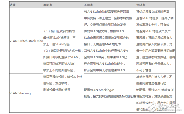
The VLAN switch stack-vlan function is similar to that of VLAN stacking (VLAN stacking, which is described in the next chapter). It is also a Layer 2 technology for encapsulating outer VLAN tags in different VLANs. Table 6-11 shows the differences between the VLAN stacking function and the VLAN stacking function.
Table 6-11 Comparison between VLAN Switch function and VLAN stacking
The VLAN Switch switch-vlan function is similar to VLAN mapping (VLAN mapping, which will be described in the next chapter), and can also implement communication between different VLANs. Table 6-12 shows the differences between VLAN mapping and VLAN mapping.
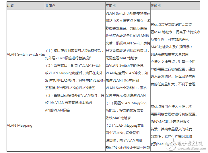
Table 6-12 Comparison between VLAN Switch and VLAN mapping
Wireless smart IoT Energy Meter is mainly used to measure three-phase active power in low-voltage network. Prepaid Energy Meter using gsm has the functions of RS485 communication,2G,4G,NB-IoT and 868MHZ/923MHZ/433MHZ Lora/Lorawan wireless communication. lorawan electricity meters is convenient for users to monitor, collect and manage electricity. prepaid electricity meter display in construction can be flexibly installed in the distribution box to realize the measurement, statistics and analysis of individual electric energy in different regions and loads.

Smart Iot Wireless Energy Meter,Three Phase Wireless Energy Meter,Iot Multi Channels Energy Meter,Smart Prepaid Energy Meter
Jiangsu Acrel Electrical Manufacturing Co., LTD. , https://www.acrel.com.pk