Radio Frequency Identification (RFID) technology is a wireless communication technology that uses radio frequency signals to automatically identify and exchange data on electronically tagged items. The RFID system is mainly composed of a reader and an electronic tag. Electronic tags are classified into active electronic tags and passive electronic tags according to different power supply methods. The distance that the reader can receive the reflected information of the electronic tag is one of the most important technical indicators of the RFID system. The reading distance is related not only to the pattern of the tag antenna, but also to the substrate material on which the antenna is placed, and to the environment in which the electromagnetic wave is transmitted. In general, the real part of the impedance of the passive electronic tag chip is small, and the imaginary part is large. The higher Q value of the tag chip makes it difficult to design a suitable antenna to achieve impedance matching with the tag chip, especially in a wider range. Within the frequency band.
In product electronic code (EPC) applications, close-range RFID frequencies are concentrated at 13.56 MHz, while long-distance RFID frequencies are located in the UHF band. Because countries and regions have different definitions of RFID applications in the UHF band, for example, the US standard is 902 MHz to 928 MHz, Europe is 865 MHz to 868 MHz, Japan is 950 MHz to 956 MHz, and China is 840 MHz to 845 MHz. Two bands from 920 MHz to 925 MHz. Therefore, the design of UHF RFID full-band covered electronic tags to meet the requirements of countries around the world, making electronic tags versatile, is a goal of electronic tag (antenna) design.
For passive electronic tags, normal operation is only possible when the tag chip receives more energy than its minimum threshold power Pth. In order to improve the reading distance, it is necessary to achieve conjugate matching between the tag chip and the tag antenna impedance. However, the tag antenna generally uses a deformed dipole antenna, and its resonance point is not necessarily an impedance matching point. Electromagnetic coupling feeds solve this problem very well. With a feed unit, two uniformly distributed radiating elements make up the double-radiation side antenna to achieve high gain, but the omnidirectionality is not good. A UHF omnidirectional antenna, although the bandwidth can be achieved, the resonance depth is not enough (S11 "-10 dB" and has a large size. In this paper, a non-uniformly distributed bending branch is used as the coupling unit, and a tag antenna is designed. The bandwidth (S11 "-22 dB" is 180 MHz, which not only covers the UHF full band, but also has better resonance depth and smaller. The size of the tag antenna. On this basis, the distance between the sensing unit and the feeding unit and the performance of the tag antenna when the shape of the feeding unit is rectangular, triangular or trapezoidal are further studied.
1 Coupling principle analysisThis antenna model can be equivalent to the antenna model shown in FIG. When the parasitic element is infinitely long, the model of Fig. 1 can be equivalent to the equivalent circuit model shown in Fig. 2.
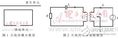
In Figure 2, the parasitic element is equivalent to L1, R, C of the left loop, where R is equivalent to the self-resistance of the radiator. The feed unit is equivalent to the right loop, and L2 is equivalent to the self-inductance of the feed unit. Since the self-impedance of the feed unit is very small, it is ignored in the equivalent circuit.
According to the reference circuit analysis theory, the circuit column KVL of Figure 2 can be obtained:
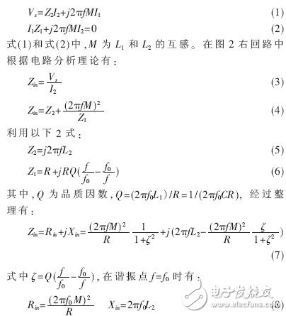
It can be seen from equation (8) that the real part of the impedance of the resonant state is only related to the mutual inductance, and the imaginary part is related to L2. Since the mutual inductance M is related to the coupling distance, the real part of the antenna impedance is related to the distance of the parasitic element from the feeding unit, and the imaginary part is only related to the shape of the feeding unit itself. Thus, it can be seen that the coupling loading near the resonance point can play a separate adjustment effect on the real part of the antenna.
2 Antenna design and researchA tag antenna structure in which branches of a parasitic element portion are evenly distributed. In order to achieve impedance matching between the tag antenna and the tag chip, the branch of the parasitic unit is non-uniformly distributed. The modeling of the tag antenna is shown in Figure 3, and the structural parameters are shown in Table 1. The antenna consists of a feed ring and a radiator. The feed unit consists of a rectangle and is directly connected to the tag chip. The radiator is composed of non-uniformly distributed bent branches. In this design, when the selected chip is at 915 MHz, the externally presented impedance is Z = 18.1 - j149 Ω, following the ISO-18000 6C protocol. In order to achieve maximum power transfer between the tag chip and the tag antenna, the required antenna impedance should be 18.1 + j149 Ω at the resonant frequency.
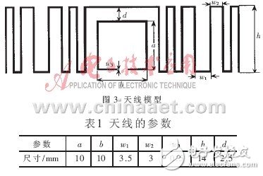
The antenna shown in Figure 3 is etched on a FR4 dielectric substrate with a thickness of 0.2 mm and a relative dielectric constant of 4.4. The antenna size is 50 mm & TImes; 20 mm.
Based on the above discussion, the effect of the distance of the parasitic element from the feed point and the shape of the feed unit on the antenna performance is now investigated.
2.1 Influence of coupling pitch on antenna performance
It can be seen from the above analysis that according to the formula (8), when the antenna is in the resonance state, the real part of the impedance is only affected by the mutual inductance, and the mutual inductance is related to the spacing of the parasitic unit and the feeding unit. It can be seen from Fig. 5(b) that as the pitch increases, the real part of the antenna impedance decreases while the imaginary part remains substantially unchanged, which is basically the same as the theoretical analysis.
Marine flowmeter is divided into LC elliptical gear flowmeter and lxz Spiral Rotor Flowmeter. It is widely used in commercial trade measurement in shipbuilding, petrochemical and other departments And engineering management control.
Marine flowmeter is a precision instrument used to measure liquid flow. It is a direct reading cumulative instrument. It is a positive displacement flowmeter that measures the total liquid flow through the pipeline. Elliptical gear flowmeter can select two counting mechanisms: mechanical display meter and electronic display meter. The display meter has the functions of displaying cumulative flow, instantaneous flow and zero return, which can realize on-site display and remote control. For different measuring media (acid, alkali, organic liquid, oil, food, etc.), the flowmeter can be made of different materials (cast steel, stainless steel and 316), which is suitable for flow measurement in industrial departments such as chemical industry, petroleum, medicine, electric power, metallurgy and food. The flowmeter with sending function can be matched with hy-908 series flow totalizer and other instruments of the company, which is convenient for centralized detection, output standard signals, automatic control and data processing, and can be directly connected with the computer.
Marine Flowmeter,Marine Gear Flowmeter,Stainless Steel Marine Flowmeter,Marine Flowmeter For Marine
Taizhou Jiabo Instrument Technology Co., Ltd. , https://www.taizhoujiabo.com