Label: Level Controller Inverter
This article refers to the address: http://
First, the principle of control
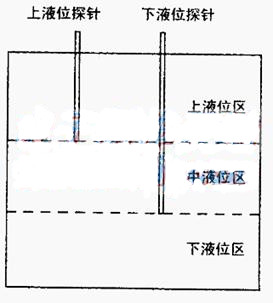
Most general-purpose inverters can operate different frequencies under different conditions. This is called multi-step frequency operation in Fuji 5000G11S/P11S series inverters, and it is called constant speed operation in ABBACS510-01 series inverters. The liquid level controller is to let the pump select different speeds according to the liquid level, so that the pump operation can achieve macro stability. As shown in the figure below, the controller uses two position probes to divide the pump pool into three liquid level zones. When the liquid does not touch the lower level probe, the inverter works in the lowest frequency zone; When it is in the middle of the two probes, the inverter works in the middle frequency zone. When the liquid level touches both probes at the same time, the inverter is in the high frequency zone.
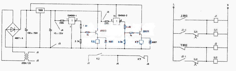
The liquid level controller is mainly composed of two parts: a liquid level sensing circuit (weak part) and a delay control circuit f. The liquid level sensing circuit is shown in the figure above, and its core is a 6-inverter CD4069. This circuit has two position detections. Only two inverters are used. The medium between the liquid level probe and the ground is different. The resistance value is also different. The input bias of the inverter changes accordingly. The output potential is changed. It is also different to control the corresponding relay.
When the medium is a slurry or the like, the input of the inverter is low, the output is high, and the relay is driven by the transistor S9013; when the medium is air, the input is high, the output is low, and the relay does not operate. (4069 a total of 6 inverting gates, the input end of the unused door must be grounded, because the detection line is long, the gate of the door, the input of the door 2 in series with the 200kΩ resistor is very important, can not be omitted). This controller can be expanded to multiple channels as needed. It should be noted that the upper liquid level relay of the controller uses a normally open contact, and the lower liquid level relay K uses a normally closed contact, and the type of the relay is JZC-23F/DC12V. The schematic diagram of the delay control circuit is shown below. The parts SJ1 and SJ2 are JS14P/220V 1~99s adjustable time relays, which are used to prevent the inverter from vibrating at the junction of two liquid levels. When the liquid level is detected to change, the new state should be maintained for a period of time. The length of this time can be manually set according to the site conditions. J1 and J2 are small 220V AC relays.
Second, installation and commissioning
The liquid level sensing part is placed on a suitable experimental circuit board and loaded into an empty time relay (model JS14P), mainly using its 8-pin male and female. The wiring of 8 feet is J1~J8 in the above picture, J1 and J2 are connected to 220 AC power supply, J3 is connected to the pump pool ground, J4 is connected to the liquid level probe, J5 is connected to the liquid level probe, and J6 is connected to the relay output common line. J7 is connected to the liquid level relay output (with open contact inside), and J8 is connected to the liquid level relay output (using normally closed contact inside).
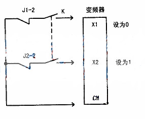
Connect the lines of the high-voltage part as shown below and place them in the appropriate distribution box. The liquid level probe is preferably made of stainless steel. The wiring should be firm and reliable. The stainless steel pipe is covered with PVC pipe. The place where the fixed bracket is in contact with the fixing bracket should be reinforced with cable sheath. The installation place should be kept dry, and the bracket should be higher than possible. The overflow liquid level is 30-40cm. Take the Fuji 5000G11S/P11S series inverter as an example to explain how the liquid level controller is connected to the inverter and set the inverter. The liquid level controller is connected to the inverter as shown on the right, K is a double-conversion switch, and the two turns to the left are connected. At this time, the liquid level is controlled; when the two are connected to the right, the manual control is performed. In the liquid level control state, the manual potentiometer cannot adjust the inverter; when the control state is manually adjusted, the liquid level control does not work. J1-2 and J2-2 are a pair of normally closed contacts of J1 and J2 in the following figure. Xl, X2, CM are the terminals of the inverter. Enter the inverter parameter adjustment state, adjust the parameter E01 to 0, E02 to 1, E03 to 2, C05 to 26 (lower level frequency), C06 to 34 (upper level frequency), C07 to 30 (middle level frequency) For detailed instructions, please refer to the corresponding inverter operating instructions. It should be noted that for the Fuji inverter, the common terminal CM is the common ground line in the inverter. For the ABB converter, the common terminal CM is connected to the positive 24V power supply in the inverter. After adjustment, you can use the liquid level to control the speed of the pump.
Tractor Autopilot Navigation,Gps Navigation System,Gps Autopilot,Unmanned Driving System
Xuzhou Jitian Intelligent Equipment Co. Ltd , https://www.jitianequipment.com