Zinc-manganese dry battery charger with timing and charging indication function, its charging current is 5OmA, can be used to charge the fully sealed ordinary dry battery with the terminal voltage of 1.35~1/4V.
Circuit Operation Principle The zinc-manganese dry battery charger circuit consists of a power supply input voltage regulator circuit, a charging circuit and a timing control circuit, as shown in Figure 5-124. The power input voltage stabilizing circuit is composed of a power supply and a shutdown S2, a fuse FU1, a power transformer T, a rectifier diode VD, a filter capacitor C1, C3, and a voltage stabilization integrated circuit.
The timing control circuit is composed of a timing start button S1, a timing control switch S3, a timing control integrated circuit IC2, resistors R1 to R5, a capacitor C2, a stop charging indicating light emitting diode VL5, VL6, a transistor V and a relay K.
The charging circuit is composed of a potentiometer RP, resistors R6~R13, charging indicating LEDs VL1~VL4 and fuses FU2~FU5.
Turn on S2, AC 220V voltage after T step-down, VD rectification and C3 filtering, one way as the input voltage of the charging circuit; the other way is regulated by IC1 to provide +12V working voltage for IC2.
Press the timer start button S1, IC2 starts timing work; its 3 feet output high level to make V turn on, K pulls in, K's normally open contact is connected, battery GB1~GB4 starts charging, and VL1~VL4 points bright.
S3 is used to set the charging time. The timing range is 4th in 3h, 5h, 7h and 9h. When charging the AA type dry battery, the optimal charging time is 5h; when charging the C type dry battery, the optimal charging time is 9h.
When the timing time is over, the 3 pin of IC2 outputs a low level, so that V is cut off, K is released, and the battery stops charging; at the same time, the 2 pin of IC2 changes from low level to high level, so that VL5 and VL6 are lit, indicating charging. End. 
Adjust the resistance of the RP to change the charging voltage and charging current.
Component selection
R1~R5, R6, R8, R1O and R12 are all selected from 1/4W metal film resistors; R7, R9, R11 and R13 are all 1W metal film resistors.
The RP uses a 2W wirewound variable resistor.
C1 selects monolithic capacitors; C2 selects aluminum electrolytic capacitors with a withstand voltage of 16V; C3 selects aluminum electrolytic capacitors with a withstand voltage of 5OV.
VD selects 1N4004 or 1N4007 silicon rectifier diode for use.
VL1~VL6 select φ3mm LEDs.
V selects S805O or C8050 type silicon NPN transistor.
IC1 selects LM7812 type three-terminal regulator integrated circuit; IC2 selects ZN1034 type timing integrated circuit.
K selects 4098 type 12V DC relay.
S1 selects the micro-motion button; S2 selects 250V, the contact current capacity is 5A power switch; S3 selects the single-pole four-position switch.
T selects 3~5W, the secondary voltage is 12~15V power transformer.
DIP Sockets & Adapters
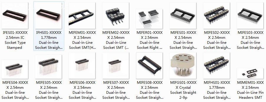
Precision machined Dual In-line Package (DIP) Sockets and Adapters accommodate applications from surface mount to thru-hole. Screw-machined terminals offer superior quality for long-term durability.
Overview of DIP Sockets & Adapters
DIP Sockets and Adapters allow for quick and easy device replacement, upgrade, or repair in test and production applications, while protecting DIP devices from exposure to heat during board processing. Screw-machined terminals with redundant, multi-finger contacts ensure reliable performance even in harsh environments.
Automated assembly compliant.
Wide range of patterns and terminal styles, from 8 to 64 pins.
Optional Tape Seal on terminals protects contacts from contaminants during board processing.
Solder Preform terminals available for mixed SMT and thru-hole process applications.
RoHS Compliant insulators and terminals are compatible with lead-free processing - select either Matte Tin/Gold (MG) or Gold/Gold (GG) plating.
Our large selection of DIP sockets ranging from 1 to 48 contacts can provide a highly reliable connection between your integrated circuit (IC) devices and PCBs. Antenk offers DIP sockets in a wide variety for high reliability. Positions range from 1 to 48, and termination options include through hole and surface mounting, solderless zero profile, four-finger inner contact and dual leaf contacts, as well as a variety of plating options.

Antenk DIP Sockets Product Features
1 to 48 positions
Precision four-finger inner contacts or dual leaf contacts are optional
Open frame and closed frame housings
Available with a variety of plating options
Four-Fingered Contacts
Precision machined or stamped four-finger inner contacts with open or closed frame housings facilitate highly reliable DIP sockets.
Dual Leaf Contacts
Dual leaf contacts provide a cost effective solution to the DIP socket design with superior handling characteristics.
DIP Sockets Adapters,DIP Integrated circuit Sockets,Dual In-line Package Sockets,Dual In-line Package Adapters,IC Socket, IC Sockets Adapters
ShenZhen Antenk Electronics Co,Ltd , https://www.antenkconn.com