Binary Image means that there are only two possible values ​​or grayscale states for each pixel on the image. People often use black and white, B&W, and monochrome images to represent binary images. A binary image means that there are only two gray levels in the image, that is, any pixel in the image is not 0 or 1, and there is no other transition gray value.
Corrosion and expansion are the basis of morphological processing, and many morphological algorithms are based on these two operations.

Figure 1 Using corrosion to remove parts from the image
Figure 1a is a binary image of a 486x486 connection template. Figures 1b~d are etched using 11x11, 15X15 and 45X45 templates, respectively. We see from this example that the corrosion shrinks or refines the objects in the binary image. In fact, we can think of corrosion as a morphological filtering operation that filters out image details smaller than the template from the image.
2 corrosion algorithmUse white corrosion:
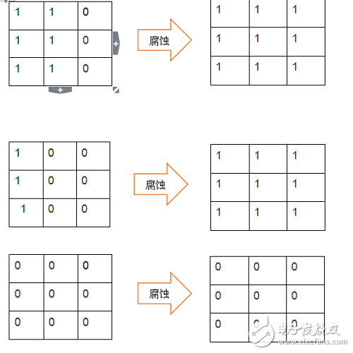
Figure 2 Corrosion demonstration
In the corrosion algorithm of binary image, we use the binary image 3x3 image matrix. As you can see from Figure 2, when the nine grids are not all '0' or '1', the values ​​of the nine grids will eventually pass through the corrosion algorithm. Becomes '1'; if all nine are '1' or '0', then the final result is all '1' or '0'.
3 FPGA corrosion algorithm implementation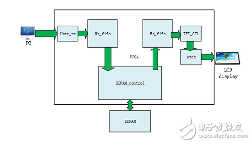
Figure 3 Binary image corrosion FPGA module architecture
In Figure 3 we use the serial port to transfer the picture, the binary image is passed in.
FPGA source code:
/*
Module name: binary_image_etch.v
DescripTIon: binary image etch
*/
`TImescale 1ns/1ps
Module binary_image_etch(
Input clk, //pixel clk
Input rst_n,
Input hs_in,
Input vs_in,
Input [15:0] data_in,
Input data_in_en,
Output hs_out,
Output vs_out,
Output reg [15:0] data_out,
Output data_out_en
);
Wire [15:0] line0;
Wire [15:0] line1;
Wire [15:0] line2;
Reg [15:0] line0_data0;
Reg [15:0] line0_data1;
Reg [15:0] line0_data2;
Reg [15:0] line1_data0;
Reg [15:0] line1_data1;
Reg [15:0] line1_data2;
Reg [15:0] line2_data0;
Reg [15:0] line2_data1;
Reg [15:0] line2_data2;
Reg data_out_en0;
Reg data_out_en1;
Reg data_out_en2;
Reg hs_r0;
Reg hs_r1;
Reg hs_r2;
Reg vs_r0;
Reg vs_r1;
Reg vs_r2;
Wire[18:0] result_data;
Line3x3 line3x3_inst(
.clken(data_in_en),
.clock(clk),
.shifTIn(data_in),
.shiftout(),
.taps0x(line0),
.taps1x(line1),
.taps2x(line2)
);
//------------------------------------------------ ----------------------
// Form an image matrix of three mulTIplied by three
//------------------------------------------------ ----------------------
Always @(posedge clk or negedge rst_n) begin
If(!rst_n) begin
Line0_data0 <<= 16'b0;
Line0_data1 <<= 16'b0;
Line0_data2 <<= 16'b0;
Line1_data0 <<= 16'b0;
Line1_data1 <<= 16'b0;
Line1_data2 <<= 16'b0;
Line2_data0 <<= 16'b0;
Line2_data1 <<= 16'b0;
Line2_data2 <<= 16'b0;
Data_out_en0 <<= 1'b0;
Data_out_en1 <<= 1'b0;
Data_out_en2 <<= 1'b0;
Hs_r0 <<= 1'b0;
Hs_r1 <<= 1'b0;
Hs_r2 <<= 1'b0;
Vs_r0 <<= 1'b0;
Vs_r1 <<= 1'b0;
Vs_r2 <<= 1'b0;
End
Else if(data_in_en) begin
Line0_data0 <<= line0;
Line0_data1 <<= line0_data0;
Line0_data2 <<= line0_data1;
Line1_data0 <<= line1;
Line1_data1 <<= line1_data0;
Line1_data2 <<= line1_data1;
Line2_data0 <<= line2;
Line2_data1 <<= line2_data0;
Line2_data2 <<= line2_data1;
Data_out_en0 <<= data_in_en;
Data_out_en1 <<= data_out_en0;
Data_out_en2 <<= data_out_en1;
Hs_r0 <<= hs_in;
Hs_r1 <<= hs_r0;
Hs_r2 <<= hs_r1;
Vs_r0 "= vs_in;
Vs_r1 "= vs_r0;
Vs_r2 "= vs_r1;
End
End
//------------------------------------------------ -----------------
// line0_data0 line0_data1 line0_data2
// line1_data0 line1_data1 line1_data2
// line2_data0 line2_data1 line2_data2
//------------------------------------------------ ----------------
Always @(posedge clk or negedge rst_n) begin
If(!rst_n)
Data_out <<= 16'h0000;
Else if(data_out_en1)
If((line0_data0 == 16'h0000) && (line0_data1 == 16'h0000) && (line0_data2 == 16'h0000) && (line1_data0 == 16'h0000) && (line1_data1 == 16'h0000) && (line1_data2 = = 16'h0000) && (line2_data0 == 16'h0000) && (line2_data1 == 16'h0000) && (line2_data2 == 16'h0000))
Data_out <<= line1_data1;
Else if((line0_data0 == 16'hffff) && (line0_data1 == 16'hffff) && (line0_data2 == 16'hffff) && (line1_data0 == 16'hffff) && (line1_data1 == 16'hffff) && (line1_data2 == 16'hffff) && (line2_data0 == 16'hffff) && (line2_data1 == 16'hffff) && (line2_data2 == 16'hffff))
Data_out <<= line1_data1;
Else
Data_out <<= 16'hffff;
End
Endmodule
4 experimental results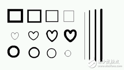
Figure 4 Experimental original image
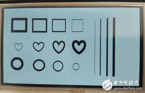
Figure 5 shows the original image
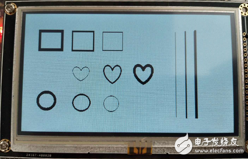
Figure 6 Results after corrosion
Result analysis:
Comparing Fig. 5 with Fig. 6, the thinnest pattern in Fig. 5 has disappeared in Fig. 6, and the thicker lines are relatively thinner, and the experiment is successful. If you want to do more corrosion, you can use a larger template.
ZGAR PCC
ZGAR electronic cigarette uses high-tech R&D, food grade disposable pod device and high-quality raw material. All package designs are Original IP. Our designer team is from Hong Kong. We have very high requirements for product quality, flavors taste and packaging design. The E-liquid is imported, materials are food grade, and assembly plant is medical-grade dust-free workshops.
From production to packaging, the whole system of tracking, efficient and orderly process, achieving daily efficient output. We pay attention to the details of each process control. The first class dust-free production workshop has passed the GMP food and drug production standard certification, ensuring quality and safety. We choose the products with a traceability system, which can not only effectively track and trace all kinds of data, but also ensure good product quality.
We offer best price, high quality Vape Device, E-Cigarette Vape Pen, Disposable Device Vape,Vape Pen Atomizer, Electronic cigarette to all over the world.
Much Better Vaping Experience!


ZGAR PCC E-Cigarette Vape Pen,ZGAR PCC Device Vape,ZGAR PCC Vape Pen Atomizer,Latest Disposable E-Cigarette OEM vape pen,ZGAR PCC electronic cigarette
ZGAR INTERNATIONAL(HK)CO., LIMITED , https://www.sze-cigarette.com