The voice group chat system is composed of multiple audio circuits. In order to make the call orderly, it is required to control the output of each audio signal through the audio exchange circuit. The audio switching circuit is mainly used to complete the switching of the voice signal to realize the voice communication of the same frequency terminal. After comprehensive consideration of reliability, economy, compatibility and availability, the control system uses AT89S52 MCU and switching control matrix device MT8816AE. Among them, AT89S52 type MCU has the advantages of practical, low price, low power consumption, fast speed, small size and strong function; MT8816AE is a CMOS monolithic integrated circuit with low power consumption and high reliability.
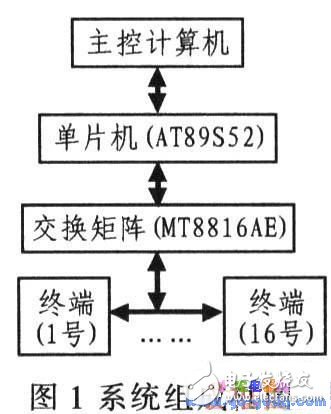
2. Control system composition and circuit designFigure 1 shows the block diagram of the entire system. It consists of a main control computer, an audio exchange circuit, and terminal equipment. Its working principle is: after the host computer captures the working frequency of the terminal. The instruction is issued to the switching control microcontroller, and the switching matrix is ​​under the control of the single chip microcomputer. Terminals connected to the same frequency point. The control system circuit comprises a switch control matrix circuit, a switch control single chip circuit and a serial interface circuit.
2.1 Switch Control Matrix Circuit Design
The MT8816AE contains an 8x16 switch array with 7 to 128 line decoders and latches. Any of the matrix switches can be addressed by selecting the 7 appropriate address bits. Add 1 or 0 to the DATA input of the device to turn the selected switch on or off. STROBE is a latched signal, and the device select (CS) signal allows the switch arrays to be connected in series to expand the tolerance of the matrix.
In the case where the session size is not large, according to the matrix switch specification, the operational relationship between the switching circuit capacity n and the required number of MT8816AE IV: N = (n / 8) (n / 16). Taking 16 system terminals as an example, two MT8816AEs are required. Define the row of the switch array, that is, X is the terminal; define the column of the switch array, that is, Y is the terminal. In the MT8816AE chip 1: X0~X15 are connected to terminals 0-15, respectively; Y0~Y7 are connected to terminals 0~7, respectively, to realize the transceiver intercommunication of any intra-frequency terminal in 0~7. And 8~15 terminal transmission, 0~7 collection function. In the MT8816AE film 2: XO~X15 are connected to terminals 0~15, respectively; Y0~Y7 are connected to terminals 8~15 respectively, to realize the transceiver intercommunication of any intra-frequency terminal within 8~15, and 0~7 Terminal transmission, 8 to 15 collection function. In this way, two pieces of MT8816AE are connected in series. Full-duplex voice communication of 16 terminals can be realized.
2.2 Switch Control Single Chip Circuit Design
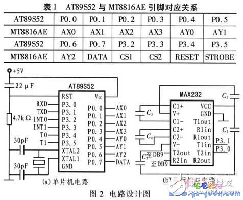
The AT89S52 is connected to the serial port of the main control computer through the MAX232, and controls the on/off of the MT8816AE switch array according to the command data frame received from the host computer. Among them, AT3.0s52's P3.0 (RXD) and P3.1 (TXD) are the input and output terminals of the serial interface, and are connected with the MAX232 serial port circuit; the reset circuit adopts the power-on reset mode, and the capacitance of the peripheral circuit is 22μF. The pull-down resistor is 4.7 kΩ; the external oscillator of 11.0592 NHz and two 30 pF electrolytic capacitors form an oscillating circuit. Figure 2a shows the switching control microcontroller circuit. Table 1 shows the correspondence between the AT89S52 and biT8816AE pins.
2.3 serial interface circuit design
The AT89S52 is connected to the host computer via the RS232 interface. Because the respective working voltages are different, the MAX232 is used to achieve level conversion to meet the system operating voltage requirements. Its serial interface circuit is shown in Figure 2b.
3, software design3.1 Communication Protocol
The switching function of the circuit is realized by programming a communication protocol. The principle is: a frame data is sent by the main control computer, and is sent to the AT89S52 single chip through the RS232 standard interface, and then the switching matrix circuit is controlled to be turned on and off according to the communication frame command. Table 2 gives the data frame structure definition.
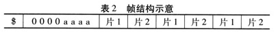
In Table 2, $ is the sending flag; aaaa is the number of 16 terminal switches; slice l is the on/off status of 0~15 machine and 0~7 machine control byte: slice 2 is 0~15 machine and 8 The on/off condition of the ~15 machine. In the case of a turn-on, the highest bit of the control byte is "1"; in the case of a disconnect, the most significant bit of the control byte is "0". Sending $80 is the MT8816AE reset control signal. For example, sending $048133 means that the on/off status of four terminals is changed, that is, the terminals No. 1 and No. 0 are connected. Controlled by slice 1; disconnected from terminals 3 and 10. Controlled by slice 2.
3.2 main control program design
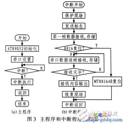
Figure 3a shows the main program flow of the AT89S52 microcontroller. First, initialize the microcontroller, define the internal clock, complete the interrupt and serial port settings, once the interrupt request, the CPU is woken up, then enter the interrupt program (Figure 3b), receive the serial command data frame. According to the command requirements, the functions such as switch matrix reset and voice channel interruption are executed. After the execution is completed, the system returns to the standby state.
The system design can be widely used in small conference systems or voice group chat systems, or can realize audio exchange of multiple voice terminals in a small range without relying on the telecommunication network, that is, switching of voice signals, so that the calls can be arranged in an orderly manner. In addition, the call and response functions of voice communication between communication stations can be simulated by voice communication of the same frequency analog terminal. Tested and tested by the test circuit showed. The system meets the technical requirements of audio exchange control, and the performance and various technical indicators basically meet the design requirements. The switching of the switching circuit is accurate and smooth, and the operation of the single-chip microcomputer is reliable and stable, and the audio channel of each channel is accurately switched. Improve the reliability and stability of the switching circuit.
Shenzhen ChengRong Technology Co.,Ltd. , https://www.dglaptopstandsupplier.com