Here we talk about the use of 51 single-chip software to decrypt the method First of all we read the connection I posted out should know that the coding is nothing more than a low level.
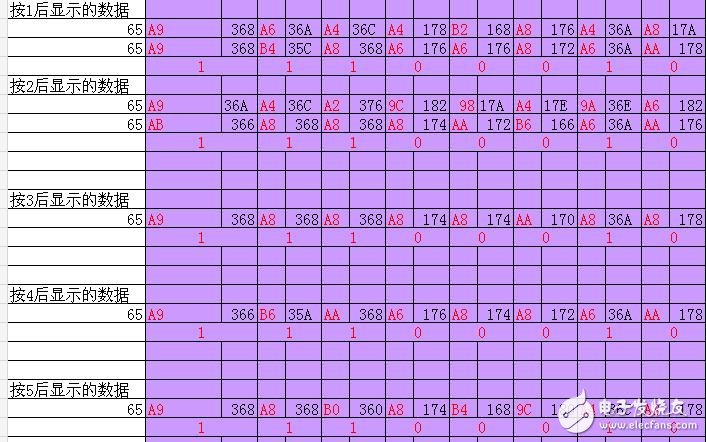
Specifically how we record this rule is very simple. We use the timer to record each high and low time and then display on the digital tube. Set 2 seconds to display a data and record it with EXCLE.
Then use a pencil or whatever drawing software to draw it out and mark it as a low-level high and compare the difference between the different keys.
Now give a practical example
Universal remote control board everyone should know it
The related pictures of this theme are as follows: Picture 04.jpg
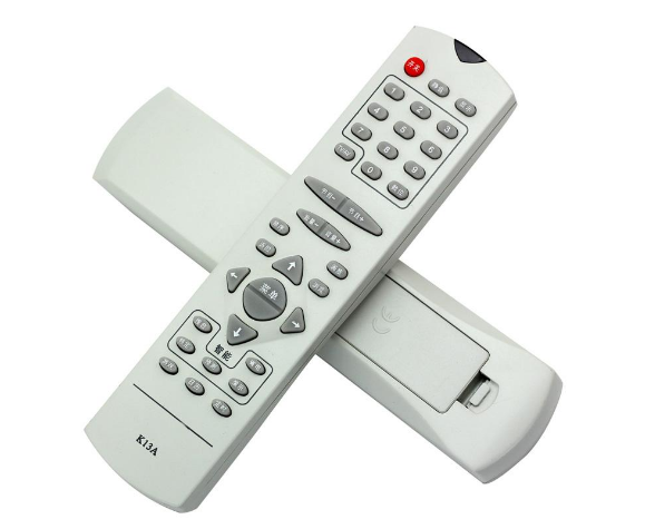
You can buy a few bucks or so and put on a battery to set up a good model (this example sets up Changhong if you use your home's remote control board so you don't have to set up)
Microcontroller power on SM0038The key procedure is as follows: (here I would like to encourage you not to think that the program is complete and can be directly burned to see the results. In fact, I said in a post that you can see the program see the key core code, so you have improved Can find out the key code among them Other interfaces such as SM0038's interface digital display, etc. are added to the line. The result of this program is to put the number of pulse waves and the time of each high and low level in the register. So since you have to do is to use their own microcontroller to register the value of the register to the digital tube to record the data and then analyze the law to find out the results you want in the process I believe in this process is like doing brick research Will enjoy this process)
Mov r5, #0 ; number of time values ​​used to record the saved
Mov r1, #bmhcq ; High and low width value buffer
Dec r1
Jb p3.6, $; waiting to go low, ie waiting for a key
Next: setb tr1 ; Start timer 1
Jnb p3.6,$ ; waiting to go high to measure low time width
Clr tr1 ; turn off timer 1 ; 1US
Inc r5 ; number of time values ​​plus 1 ;1
Inc r1 ;1
Mov @r1,th1 ; Save low time value, save first 8 bits high, then save low 8 bits; 2US
Inc r1 ;1
Mov @r1,tl1 ;2
Mov th1,#0 ; re-initial value; 2
Mov tl1, #13;13 is the time elapsed from the stop of T1 to the restart of T1; 2
Setb tr1 ; restart timer; 1
Jb p3.6,$; Waiting to go low
Clr tr1 ; Turn off timer 1 ; 1
Inc r5 ;1
Inc r1 ;1
Mov @r1,th1 ; holds high time value; 2
Inc r1 ;1
Mov @r1,tl1 ;2
Mov th1,#0 ; re-initial value; 2
Mov tl1, #15;15 is the time elapsed from the stop of T1 to the restart of T1; 2
Ajmp next ; Loop detection until T1 overflows when the remote controller is pressed without keys; 2
Ajmp $
;-----------------------------------------
Timer 1 interrupt program
When an interrupt is generated when no key is pressed on the remote controller, the high and low time values ​​in BMHCQ are converted into BCD codes and displayed.
;-----------------------------------------
T1zd:
Setb tr0 ; Start T0
Clr tr1 ; Close T1
Setb et0 ; T0 open interrupt
Mov a,r5
Mov r2,a
Mov r3,#0
Lcall hextoxcq
Lcall display
Jb yszt,$ ; Delay for a period of time to record the displayed time value
Setb yszt
Mov r0,#bmhcq
Dispnext: mov a, @r0 ; Extract the time value (16 bits) from BMHCQ in turn. Tune the BTOD subroutine and convert it to a 5 bit BCD code and place it in XCQ.
Mov r3,a ; Take the high 8 bits
Inc r0
Mov a, @r0
Mov r2,a ; take the lower 8 bits
Inc r0
;lcall BtoD ; Put the high or low time value into BCD code in XCQ
Lcall HEXtoXCQ ; Put the high or low time value into hexadecimal LED code in XCQ
Lcall display ;display
Cpl p2.5 ; Change the state of the indicator lamp to show the change of display content
Jb yszt, $ ; delay time for transcript time value
Setb yszt
Djnz r5,dispnext ;get the time value is not displayed then continue
Sjmp $ ; Display is complete, stepping here
reTI
HEXtoXCQ:
Push 00h
Mov r0,#xcq
Mov a,r2
Anl a,#0fH
Mov dptr,#LED
Movc a, @a+dptr
Mov @r0,a
Inc r0
Mov a,r2
Swap a
Anl a,#0fH
Mov dptr,#LED
Movc a, @a+dptr
Mov @r0,a
Inc r0
Mov a,r3
Anl a,#0fH
Mov dptr,#LED
Movc a, @a+dptr
Mov @r0,a
Inc r0
Mov a,r3
Swap a
Anl a,#0fH
Mov dptr,#LED
Movc a, @a+dptr
Mov @r0,a
Inc r0
Mov @r0,#7eh
Inc r0
Mov @r0,#7eh
Pop 00H
Ret
Led: db 7eh, 30h, 6dh, 79h, 33h, 5bh, 5fh, 70h, 7fh, 7bh, 77h, 1fh, 4eh, 3dh, 4fh, 47h
;---------------------------------------------
; Put the R3R2 high or low time value into BCD code in XCQ
;---------------------------------------------
BtoD:
Push 00h
Mov r0,#BCD
Mov r4,#3
Bd0: mov @r0,#0 ; BCD buffer cleared
Inc r0
Djnz r4,bd0
Mov r6,#16
Bd1: clr c ; Converts 16-bit binary value in R3R2 to 3-byte BCD code into BCD buffer
Mov a,r3
Rlc a
Mov r3,a
Mov a,r2
Rlc a
Mov r2,a
Mov r4,#3
Mov r1,#bcd
BD3: mov a, @r1
Addc a,@r1
Da a
Mov @r1,a
Inc r1
Djnz r4,bd3
Djnz r6,bd1
Mov r0, #xcq ; Store conversion results from BCD buffer into XCQ
Mov r1,#bcd
Mov r4,#3
Bd4: mov a,@r1
Xchd a,@r0
Inc r0
Swap a
Xchd a,@r0
Inc r0
Inc r1
Djnz r4,bd4
Pop 00h
Ret
Through the above program we read out the essence of the code after pressing a key
So hands-on drawing down to find the law decoding
I sent out my example waveform decoded by Changhong
The related image of this theme is as follows: 01.jpg
01. JPG is the same 8 high and low pulses of all keys in the beginning of the pulse
The related image of this theme is as follows: 02.jpg
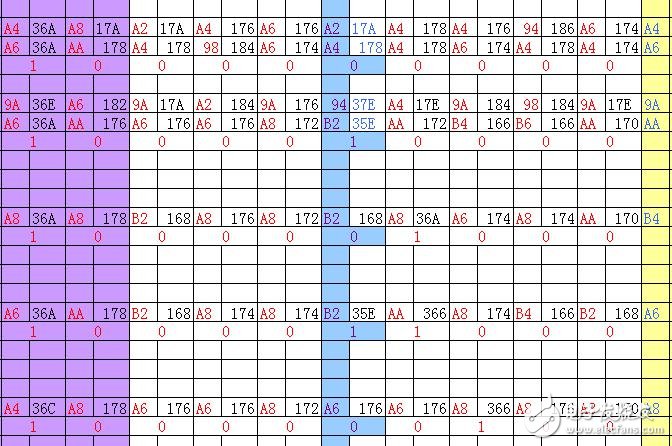
02. JPG Everyone notices that there are only 3 pulses in the middle of the different keys. The change is EXCLE's W column -AC column and these 3 digits are the key 01 for our decoding. 8 digits in JPG Everyone should see that all the keys are the same 11100010 behind 02. In JPG we sort out the key code
Press 1 key 00000000 00H
Press the 2 key 00010000 10H
Press 3 button 00001000 08H
Press 4 key 00011000 18H
Press the 5 key. . . . .
Do not write behind
For the sake of everyone clearly visible, I have drawn the final waveform 03. JPG stick out everyone see the law
The related image of this theme is as follows: 03.jpg
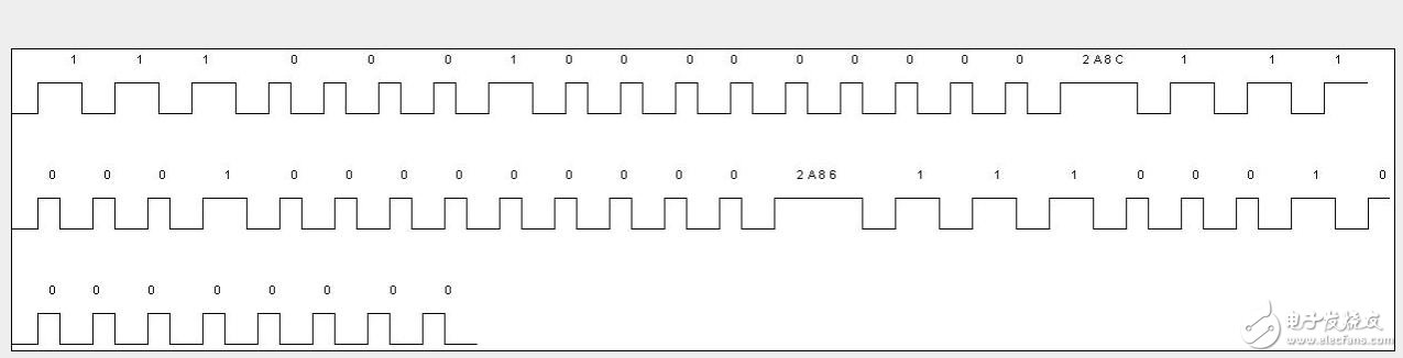
Then we analyze how to decode it. I believe that this step should be very simple. For example, in this example we found that the part of the key code change is completely repeated. So why not completely read the following code? The pulse is placed in the register and then jumped with the comparison instruction. The following is the decoding program for this waveform diagram. I believe we can use it to get it done with the weapon in our hands.
When I write here, I feel very confused and feel that I have not been able to simplify a lot of specific issues or that I have to understand and understand them myself.
The program can't read it. ? So OK to turn over the instructions and check the books one by one to see the program. I'm sure that all of them are compiled.
The following is the key code of the decoding program:
DYKJZ: JB P3.6, $
LCALL YKJM; core decoding code subroutine
Cpl a
Jz no ; Judge whether it is an error code (0FFH)
Cpl a
AJMP JZPD
NO: LJMP DYKJZ
RET
JZPD: CJNE A, #09H, JZ1 ; Is the key code 09H?
AJMP KAIS ; Key code is 09H Start program ()
JZ1:; not for 09H turn first wait for the next remote button arrival
AJMP DYKJZ
RET
KAIS: ; Put the code you need to execute
For example, a single light to the microcontroller connected to the serial port with a single-chip computer to open the computer to control the music. and many more
These are not interested in the scope of this discussion can expand their own
RET
;-----------------------
Core decoding code subroutine
;-----------------------
YKJM:
PUSH PSW
PUSH 02H
PUSH 06H
PUSH 07H
PUSH B
MOV B, #0FFH
JNB TF1, JMCW; Avoid the retransmission code of the remote control by timing T1 from 0 to overflow, ie after reading a remote control button
CLR TF1 ; To wait until T1 starts timing from 0 to overflow to read the second button
; The following code is executed when the boot code is correct
; CLR YKBZ ; Clear remote control flag
JM21:
MOV R2, #16 ; 8 bits per cycle
MOV R6, #0 ; Stores the lower 8 bits of the 16-bit code
MOV R7,#0 ; Stores the upper 8 bits of the 16-bit code
JM3:
JNB P3.6, $; wait for the end of the low level, regardless of its width, because it is differentiated by the width of the high level (approximately 0.5ms) and 1 (approximately 1.6ms)
MOV TH1, #0
MOV TL1, #0
SETB TR1 ; Start T1, statistics high width
JB P3.6, $
CLR TR1
MOV A, TH1
CJNE A, #2, JM4; if the high level width value is greater than 2, then this high level is a wide pulse (1), otherwise it is a narrow pulse (0)
JM4: CPL C ; When the value of TH1 is greater than 2, C=0, when it is less than 2, C=1
MOV A, R7
RRC A
MOV R7,A
MOV A, R6
RRC A
MOV R6,A
DJNZ R2, JM3 ; read 16 bits at a time, the first reading is low, the later reading is high, the high 8 bits (data code) are stored in R7, and the low 8 bits (address code) are stored in R6
MOV A, R6
CJNE A, #47H, JMCW ; Judging whether the address code is 47H, not return error return
MOV A, R7 ; If the address code is correct, R7 is the data code
Mov r1,#jzh
Mov @r1,A
LJMP JMFH
JMCW: MOV A, B
JMFH: CLR TF1 ; T1 overflow flag cleared
MOV TH1,#0 ; Set initial value for T1 and start it
MOV TL1, #0 ; This avoids reading the same key twice (avoiding the retransmission code of the remote control)
SETB TR2
POP B
POP 07H
POP 06H
POP 02H
POP PSW
RET; At this time, if there is a problem in the boot code, address code, key code, and key-value inversion, A is the error code; otherwise, A is the key value code that was pressed.
The article is finished. I hope to study it if you have a little help and feel useful.
Celeron Mini Pc,Office Mini Pc,Mini Desktop,Linux Mini Pc
Shenzhen Innovative Cloud Computer Co., Ltd. , https://www.xcypc.com