In recent years, with the rapid development of urban public transport, the way of reporting buses in domestic buses has been greatly improved. From the traditional ticket sellers, the station has gradually changed to the use of the station to manually report the station.
This article refers to the address: http://
Although the manual station is easy to use, but because the driver needs to report the station under the premise of ensuring safe driving, there are often reports that the station is not timely, even misreported or missing, and the driver is driving. There are also security risks in the reporting. The use of automatic station reporting can greatly reduce the workload of the driver and promote the modernization of the bus system. To achieve automatic station reporting, you need to measure the location of the bus in real time to determine if the bus has arrived at the station. GPS can be used to determine the geographic location of the bus. Just compare the current location with the location data (latitude and longitude) of the bus stop to know if the bus has arrived at the station, making the station system have certain intelligence. This GPS-based intelligent reporting system can eliminate the hidden dangers caused by the driver's driving process. It is especially suitable for China's national conditions, which are caused by the rapid development of the automotive industry, and it is also possible to add relevant introductions to the city's scenic spots on key routes. The system has great potential in the field of GPS navigation and business, and has broad development prospects.
1 system plan
The GPS-based bus intelligent reporting system is a combination of mobile communication technology and GPS technology. The whole system consists of S3C24l0 ARM9 (Advanced Reduced Instruction Set Machine) development board, SIM548C GPS/GPRS module, voice broadcast module, AT89S52 microcontroller and OCMJ5X10B. LED (Light Emitting Diode) The backlight is composed of a wide temperature yellow-green screen. The GSM/GPS module consists of a GPS sub-module and a GSM (Global System for Mobile Communications) sub-module. The GPS module is responsible for GPS data reception. During the journey of the bus, the measured information of the GPS module can be automatically reported compared with the stored location information, and no special intervention is required, and certain specific information, such as travel tips and advertisement information, can be played at a fixed location. Wait. The GSM module is used for data communication between the bus and the dispatching room, realizes the joint dispatch of the bus, and realizes the dispatching function of the dispatching center to the bus.
The voice broadcast module is responsible for voice playback, and provides voice playback such as entry and exit and prompt information. The MCU module controls button scanning and LCD display.
1. 1 hardware design
The hardware part of the system is mainly composed of S3C2410 ARM9 development board, GPS/GSM module, power amplifier module, display module, voice playback module and corresponding peripheral circuits. Both the GPRS module and the GPS module are connected to the ARM processor via RS232 (serial port), while the LCD (liquid crystal display) module is controlled by the single-chip microcomputer to communicate with the ARM through the serial port. The voice playback module passes IIS (Inter IC Sound) and SPI (serial external). Set interface) to communicate with ARM. The hardware connection method is shown in Figure 1.
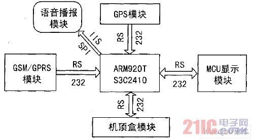
Figure 1 system hardware structure
The GSM/GPS module uses SIMCOM's GPS/GSM module, a quad-band GSM/GPRS (General Packet Radio Service Technology) wireless module that supports SiRF Star III AGPS technology.
The integration of GSM/GPRS and AGPS technology enables the module to meet the monitoring and management of GPS tracking, navigation, vehicle and ship equipment and other assets as well as other GPS applications. The keyboard scan and screen display are processed by the microcontroller. The keyboard display board mainly realizes keyboard scanning, LCD screen display and communication with the ARM processor module. The overall block diagram of the hardware system is shown in Figure 2.
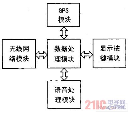
Figure 2 System composition
1. 2 overall software design
The main functions of the system are controlled by ARM, programmed in C language, and multi-threaded to process related functional modules. The relevant process is as follows: After the system initialization is completed, the location, the station and the related information are calculated according to the GPS positioning information and the line information stored by the system, and the display module in the vehicle is controlled by the ARM to display, voice play and perform to the data center. data transmission.
2 design implementation
2. 1 system initialization
Each part must be initialized with a software program before the system is running. Initialization includes the following sections:
ARM and system initialization; display button module initialization; external device, interface initialization: mainly GPS, GPRS and voice chip initialization; software system initialization: set global variables, pointers and arrays, data structure and bus information initialization.
The system software part mainly detects the GPS information in the main program, determines the current geographical location of the bus, and then decides whether to play the voice information. At the same time, you need to implement the functions required by the buttons, such as switching to manual broadcast. The software part of the system is developed based on the Linux development environment. According to the functions to be completed by the system and the operation of each module, the main program part adopts multi-threading and message queue, which can receive GPS data in time.
Because only the data of the GPRMC frame is used, the data volume of the serial communication is not large, the communication and data processing processes are relatively fast, and the system can play the report station and other voice information in time. The latitude and longitude data of each station passing by the bus needs to be measured in advance and stored in the data area of ​​the system for comparison. The GPRS information is transmitted through the serial port, using the query method, and the button is also used to receive the query to determine which function key is pressed. The software is written in C language, and after debugging, it is burned into Flash and realized offline operation.
2. 2 GPS module
Since the GPS module setting information is lost due to power failure, the GPS module is initialized every time the system is started. Set the module to output GPS information once per second.
After the system is started, the module receives the GPS information, and then parses out the GPS information, and calculates the actual distance based on the parsed latitude and longitude information compared with the site information stored in the data area. If the distance reaches the threshold, the GPS station is interrupted.
The GPS module receiving module follows the NMEA. 0183 protocol and can output data frames in multiple formats, starting with “MYMâ€. The output data is in ASCII characters and contains information such as latitude, longitude, speed, date, heading and satellite status. With more than 10 frame formats, the system uses only the GPGMC positioning data frame format.
After the system is started, the GPS module is set through the serial port. Since the system does not require real-time performance, the GPS is set to output RMC data once per second. The idea of ​​extracting the GPRMC statement is to set a data buffer and put the received GPS data into this buffer. When the buffer is full, it will find in the buffer whether to accept the GPRMC positioning statement. If it is not received, Re-receive GPS data. If the GPRMC positioning statement is found, it is also determined whether the maximum number of bytes in the buffer from the buffer is greater than 62 bytes (because the number of bytes required for the GPRMC positioning statement required in this program is 62). ), and then extract relevant information such as latitude, longitude, time and speed through multiple programs and perform related processing through the data processing thread. The system workflow is shown in Figure 3.
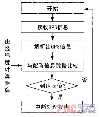
Figure 3 system workflow
2. 3 GPRS wireless communication module
Because the GSM module embeds the TCP/IP protocol, it can directly call the AT command to communicate with the server through TCP and UDP. Wireless communication is divided into two modules: the uplink data conversion module and the communication module.
The main function of the uplink data conversion module is to convert the received GPS data or related status information into a predetermined data format for communication with the main information center. The module will determine whether the data to be converted is GPS data information or related status information or both, and then select the appropriate conversion program. From the above introduction, it can be known that the received GPS data is sequentially stored in the data buffer, and what data is needed can be extracted to the corresponding position in the buffer. The data is stored in characters, so you must first convert it to shaped data when you actually use it.
The function of the downlink data conversion module is opposite to that of the uplink data conversion module. It identifies the command sent by the main information center and sends it to the vehicle terminal, and notifies the user interface module to display.
The main task of the communication module is to complete the communication between the vehicle terminal and the monitoring center. It can realize wireless communication with the main information center through the GPRS network. If the distance between the vehicle terminal and the host computer is far away, it can be directly connected to the monitoring center through the GPRS network, and it is very convenient to connect the GPRS network to the monitoring center through the SIM548C module. It is only necessary to send several AT commands to the GPRS module. However, the monitoring center must have a fixed IP of the Internet. The SIM548C module will also be activated when the vehicle terminal is activated. This is the module will automatically connect to the GPRS network to enter the command mode. After the dialing is successful, the GPRS network is connected, and then the serial communication with the SIM548C module can be read and written to achieve wireless communication with the monitoring center.
In the test, it was found that due to the difference in wireless signals, it is easy to lose the network connection with the main information center in some places where the network signal is poor. To solve this problem, multi-threaded monitoring of the network connection status in the system, once the network connection is lost, immediately reconnect with the main information center.
2. 4 voice playback module
The voice playback uses the Philips SPI interface audio chip and is driven by a sound card device under Linux. Control the audio chip through the S3C2410 SPI, transmit audio data through IIS, and finally drive the audio chip into a standard sound card device under the system.
In the voice report station, it is necessary to provide a voice signal for the speaker on the bus. The power amplifier circuit adopts a MAXIM power amplifier module, and the power amplifier module adopts a single-ended input mode, and the input negative terminal is directly grounded.
The amplifier module is a mono/stereo, Class D audio power amplifier that delivers up to 2 × 21W to 8 stereo loads or up to 1 × 42 W to mono 4 loads with efficiencies as high as 87%. The power amplifier module combines the efficiency of a Class D amplifier with the performance of a Class AB amplifier, eliminating the need for a large heat sink and reducing power consumption. The amplifier module operates from a single + 10 to + 18 V supply and can drive loads in a BTL configuration.
The player for playing the news such as the newspaper station, the advertisement and the information is selected based on the open source player, and is modified on the basis of the source code to form a play thread suitable for playing short audio, and is a system audio play function.
2. 5 display button module
The keyboard scan and screen display are processed by 51 single-chip microcomputers.
The keyboard display board mainly implements keyboard scanning, LCD screen display and communication with the ARM processor module.
The display button module communicates with the data processing module through the serial port, sends the scan button to the data processing module for processing, and simultaneously receives the display data command of the data processing module, and displays the data in the corresponding liquid crystal screen position, thereby realizing the person of the vehicle reporting system. The machine interaction function realizes the dispatch management function of the bus.
The bus automatic reporting system based on GPS and GPRS has positioning function and GPRS wireless communication function, which can realize automatic station reporting, scheduling, information transmission and reception and center communication, and has the advantages of USB interface.
It has greatly reduced the labor intensity of public transport staff and improved the scientific management of public transport.
3 Conclusion
The bus car GPS intelligent reporting system adopts GPS positioning technology and wireless communication technology, and has the characteristics of small size and accurate broadcast.
It can realize functions such as automatic station reporting, scheduling, information transmission and reception, and central communication. Through the USB interface, the system can store multiple lines, which is convenient for the bus to temporarily replace the operation line; use buttons and broadcasts as human-computer interaction interfaces to facilitate passengers to receive relevant information; and provide value-added services such as advertisements. The system provides a key bus-on-board system for establishing a complete intelligent bus dispatch management system.
A flourishing enterprise in this domain, engaged in presenting a wide range of Battery for UPS. The provided batteries are manufactured using different configurations, processes, battery backups, capacitates, and online options. Also, clients are facilitated to choose batteries from us having both online and manual systems. All installed batteries can bear the input power supply in-between 145V to 280V. The frequency rate of each battery is 50/60Hz. Moreover, entire battery systems provide the backup starting from 13minutes to 16 hours depending upon the usage.
100Ah 12V Solar Battery,12V Solar Battery,100Ah Solar Battery,Deep Cycle Solar Battery 12V 100Ah
Yangzhou Bright Solar Solutions Co., Ltd. , http://www.cnbrightsolar.com