In order to realize the precise positioning of XYZ three-dimensional workbench, a three-dimensional micro-displacement control system based on STM32F103VCT6 single-chip microcomputer and stepper motor is designed. The system can realize serial communication with the host computer, receive the command of the upper computer and feed back the processing result to the upper computer; according to the position feedback information provided by the grating sensor, the system can achieve precise positioning by adjusting the direction and speed of the stepping motor; The uniform acceleration and uniform deceleration mode adjusts the speed of the stepping motor, avoiding the lost step and impact caused by the sudden acceleration and emergency stop of the stepping motor. The measurement experiment results of the control system show that the stepping motor runs smoothly, the noise is low, the positioning accuracy is high, and the control system performance is stable and reliable.
The micro-displacement control system is an intelligent instrument that integrates various technologies such as mechanics, optics, electronics and computers. It has an extremely wide range of applications in advanced manufacturing technology and scientific research, and is an indispensable measurement device in modern industrial inspection, quality control and manufacturing technology. The micro-displacement control system generally consists of a micro-positioning mechanism, a micro-displacement detecting device and a controller. The controller is the command center of the micro-displacement system. It controls the micro-positioning platform according to a certain control algorithm to make it move according to certain rules to achieve precise positioning.
Conventional three-dimensional micro-displacement control systems generally use a stepper motor to drive a ball screw to achieve positioning. A stepper motor is an open-loop control element that converts an electrical pulse signal into an angular displacement or a linear displacement. In the case of non-overload, the speed and stop position of the motor depend only on the frequency of the pulse signal and the number of pulses, and are not affected by the load change, that is, the motor rotates by one step angle every time a pulse signal is applied, so the pulse The number and the total step angle of the motor rotation are linear. In addition, the stepper motor has only periodic errors and no cumulative error, making it very easy to control with stepper motors in the control fields such as speed and position. The main advantage of the open-loop control system of the stepping motor is that it has a simple structure and is widely used in applications where the control accuracy is not high. However, in practical applications, if the stepping motor is unreasonably controlled, the stepper motor will be lost. Or overshoot; in the open-loop control system, due to the step-by-step phenomenon of the stepping motor, it is impossible to know whether it has reached the predetermined position accurately, and high-precision positioning cannot be achieved.
In order to achieve precise positioning of the 3D workbench, the system uses a stepper motor closed-loop control system. In the system, the output of the grating sensor is used as the position feedback signal of the micro-displacement control system to realize closed-loop control. The grating sensor has a resolution of 1μm and comes with a readhead for direct output of TTL level or sine wave signals, which facilitates signal processing and connection to the control system. The control system determines whether the predetermined position has been reached by the feedback signal of the grating sensor, and then performs corresponding adjustment actions. Thereby achieving the purpose of precise positioning.
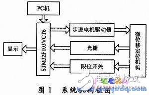
1.1 Micro-displacement control system overall design According to the design requirements of the micro-displacement control system, the positioning accuracy of the control system should be ensured first. Secondly, the structure should be simple, the cost is low, and the operation is simple. Based on the above considerations, this paper designs a micro-displacement control system as shown in Figure 1. Among them, STM32F103VCT6 MCU is used as the control core and data processor. The drive circuit is designed based on THB7128 driver chip. The positioning system adopts electric translation stage. The stepping motor drives the ball screw for positioning. The repeat positioning accuracy can reach 3μm. The upper machine adopts VB. The program design realizes the functions of sending, data processing and data display of various control commands; the communication method adopts RS 232 serial communication, the protocol is simple and the operation is convenient.
1.2 Control system peripheral circuit design
The STM32 family of microcontrollers is based on an embedded ARM Cortex-M3 core 32-bit microprocessor operating at 72 MHz with built-in high-speed memory (including 256 KB of flash and 48 KB of SRAM) with a rich set of enhanced I/O ports. And peripherals that connect the two APB buses. They also include three 12-bit ADCs, four general-purpose 16-bit timers, and two PWM timers. They also include standard and advanced communication interfaces: two I2Cs and three SPIs. 2 I2S, 1 SDIO, 3 USART, 1 USB and 1 CAN. The peripheral circuit diagram of the control system is shown in Figure 2.
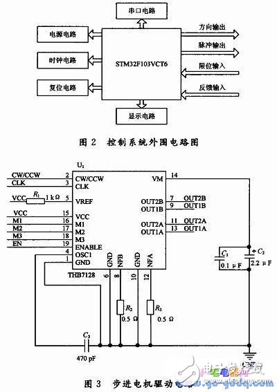
The stepping motor driven by the control system is a two-phase four-wire stepping motor. In the hardware configuration, the 12 to 14 feet of the E port are responsible for controlling the movement direction of the stepping motor, and the 1 and 8 feet of the A port and the 0 pin of the B port. As a stepper motor pulse output. The output signal is output through the 74LV245 to improve the corresponding driving capability; the 8~13 pins of the D port are the limit switch inputs, the 6th and 7th pins of the B port are the grating feedback signal inputs, and the input signals are input by photoelectric coupling, which has good The electrical insulation capability also increases the stability of the system operation.
1.3 stepper motor drive circuit design
The stepper motor drive circuit is designed based on THB7128, as shown in Figure 3. It has the following features: dual full-bridge MOSFET drive, low on-resistance RoN=0.53 Ω; maximum withstand voltage of 40 VDC, maximum current of 3.3 A (peak); various subdivision options (1,1/ 2, 1/4, 1/8, 1/16, 1/32, 1/64, 1/128); automatic semi-current locking function; built-in mixing
Attenuation mode; built-in input pull-down resistor; built-in temperature protection and overcurrent protection.
1.4 feedback circuit
The timer of the STM32 microcontroller has a specific operating mode for the feedback signal, ie the encoder interface mode. The encoder interface mode is basically equivalent to using an external clock with direction selection. This means that the counter only counts continuously between 0 and the autoload value of the TIMx_ARR register (either according to direction, or 0 to ARR count, or ARR to 0 count). Therefore, TIMx_ARR must be configured before starting counting; likewise, the trap, comparator, prescaler, trigger output characteristics, etc. still work normally. In this mode, the counter is automatically modified in accordance with the speed and direction of the incremental encoder, so the contents of the counter always indicate the position of the encoder. The counting direction corresponds to the direction in which the connected sensor rotates.
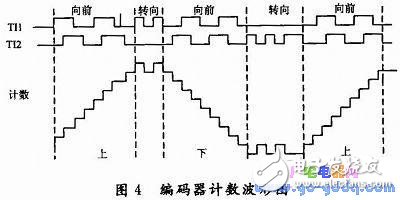
Figure 4 is an example of a counter operation showing the generation and direction control of the count signal. It also shows how input jitter is suppressed when double edges are selected; jitter can occur when the sensor is near a transition point. In this example, assume the configuration is as follows:
CC1S=01 (TIMx_CCMR1 register, IC1FP1 is mapped to TI1)
CC2S=01 (TIMx_CCMR2 register, IC2FP2 is mapped to TI2)
CC1P=0 (TIMx_CCER register, IC1FP1 is not inverted, IC1FP1=TI1)
CC2P=0 (TIMx_CCER register, IC2FP2 is not inverted, IC2FP2=TI2)
SMS=011 (TIMx_SMCR register, all inputs are valid on rising and falling edges),
CEN=1 (TIMx_CR1 register, counter enabled)
VCM (Voice Coil Motor), the Voice Coil Motor in electronics, is a kind of Motor. Because the principle and loudspeaker similar, so called voice coil motor, with high frequency, high precision characteristics.
Its main principle is in a permanent magnetic field, by changing the motor coil DC current size, to control the stretching position of the spring, so as to drive up and down movement.
VCM is widely used in mobile phone cameras to realize the function of autofocus. Through VCM, the position of the lens can be adjusted to present clear images.
VCM is include of Shield Case, Frame, F.Spacer, F.Spring, Yoke, Magnet, Coil, Carrier, B.Spacer, B.Spring, Base.
Components Vcm Gasket,Components Vcm Gaskets,Camera Vcm Terminals,No Notch Terminal
SHAOXING HUALI ELECTRONICS CO., LTD. , https://www.cnsxhuali.com