3D printing technology has developed rapidly in recent years and has been widely used in aerospace, defense, medical equipment and education. For the current 3D printers, which mainly use wired printing, which requires computers and other devices, it is not convenient to carry. This paper designs a wireless 3D printer based on wifi, which can be directly separated from the computer to realize wireless control of mobile devices for printing, which provides convenience for users.
3D printing is a kind of rapid prototyping technology. It is based on digital model files and uses materials such as plastic or powdered metal to construct objects by layer-by-layer printing. In recent years, 3D printing technology has developed rapidly and has been widely used in aerospace, defense, medical equipment, education and manufacturing. However, most of the current 3D printers still use a computer connection for operation printing, or use an SD card to store data of the printed product for printing, which sometimes causes great inconvenience to the user. Mobile devices such as mobile phones and tablets have become a must-have for people, and these products all have wifi wireless transmission. This paper designs a controller that can use mobile phone, tablet and other mobile terminal to install app application software to realize mobile device wifi wireless control 3D printer for printing. The selection, transmission and print control of the print object are performed by the mobile app software. With wifi operation, 3D printers are not limited to operating on a computer, which is convenient for users and saves the cost of use. This article focuses on the design of the wireless 3D printer controller and PC application interface.
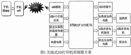
1 Wireless 3D printer controller design The core CPU of the controller is ST's STM32F103VET6 microcontroller. The control system mainly completes the data transmitted by the WiFi module; reads the 3D model data file stored in the SD card; Motor control; temperature control of the extrusion head and hot bed; extrusion head stroke control. The overall block diagram of the control system of the wireless 3D printer is shown in Figure 1.
2 system hardware circuit design
2.1 wifi communication circuit design This design uses the wifi module of ESP8266 as the main control chip. The wifi module of ESP8266 has the characteristics of simple interface, low price and high efficiency AT command, and simpler development. The ESP8266 chip has a complete and self-contained wifi network solution with high on-chip integration, including antenna switches and power management converters, so only a small amount of external circuitry is required, and the entire circuit, including the front-end module, occupies the PCB. The space is very small, designed for mobile devices and IoT applications, connecting the user's physical devices to the wifi wireless network for Internet or LAN communication. The WiFi module uses a UART to communicate with the controller. STM32 sends an AT command through the serial port TX to set the wifi working mode, UART baud rate, establishing connection and other related parameters. The USART receiving port RX of the STM32 receives the data and instructions received by the wifi module from the mobile terminal. In this way, when the mobile terminal and the 3D printing terminal establish a wireless connection, data bidirectional communication can be realized.
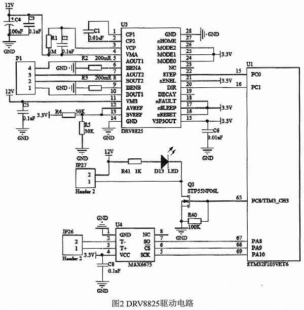
2.2 Stepper motor drive circuit design For small printers, two-phase four-wire 42 series stepper motors are generally used. STM32 controls the stepper motor by means of the motor drive circuit. In the 3D printer, the A4988 chip is generally used as the stepper motor drive, but the A4988 chip has a maximum of 16 subdivisions and the maximum output current is 2A. TI's DRV8825 stepper motor driver chip can achieve up to 32 subdivisions, and the drive current can output 2.5A, as low as 0.2 ohms on-resistance, ensuring the chip's good heat dissipation and other advantages. In addition, the chip integrates fast-responding short-circuit, over-temperature, under-voltage and cross-conduction protection circuits to detect fault conditions and quickly cut off the H-bridge to protect the motor and driver chip. This design selects DEV8825 as the stepper motor driver chip. Figure 2 shows the interface between the stepper motor drive circuit and the heating and temperature sensing circuit and the STM32. In Figure 2, P1 is the interface between the two-phase four-wire stepper motor and the DRV8825 driver circuit. The STEP step and DIR direction control pins of the chip are connected to the PC0 and PC1 pins of the STM32 for control. In this design, the subdivision has been set to 1/32 in the design of the driver circuit hardware. Sleep, reset, etc. are disabled, which can save the GPIO port of STM32. If the controller chip is sufficient, these tubes can be controlled by program. Stepping motor control for more functions on the foot.
2.3 Extrusion head temperature detection and heating circuit design Both the extrusion head and the hot bed need to maintain a relatively constant temperature during the 3D printing process. If the PLA printing material is used, the extrusion head heating temperature is generally set to 175-200 degrees. The bed temperature is set to 40-60 degrees. The temperature detection in the circuit uses the MAX6675 digital temperature conversion chip to convert the temperature of the thermistor into a digital quantity that is read by the STM32. The temperature of the extrusion head and the hot bed can be determined according to the specific use environment. The extrusion head and the hot bed temperature detection and heating circuit are the same. Here, the heating principle of the extrusion head temperature detection and heating circuit is illustrated. 2 is shown.
3 system software design
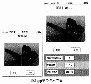
3.1 Mobile APP software design The mobile application mainly implements 3D print file selection, confirmation, 3D printer status display and wifi connection. The application uses Android programming to read the print data file and control the wifi for data transmission. It can also set the print head temperature and hot bed temperature of the 3D printer, and can receive the print head and hot bed temperature for display, and use. Material type and usage information are displayed. The main page design of the mobile application is shown in Figure 3.
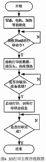
3. 2 main program flow chart software program has communication, digital signal control and data reading and processing functions, according to design requirements, software program flow chart design shown in Figure 4:
4 Conclusion With the popularity of 3D printers and mobile terminals such as mobile phones and tablets, the use of mobile terminals to control 3D printers is the future direction of 3D printers. In this paper, the realization of the wireless printing of 3D printer, the specific implementation principle and program flow are given. The STM32 microcontroller is used to improve the processing speed. The heating circuit is adjusted by PID to ensure the temperature is constant, reducing the phenomenon of broken wire and uneven thickness. The print quality. Through actual verification, the control of the 3D printer by mobile terminals such as mobile phones can be realized, and the design improves the print quality. Wireless printing provides convenience for users to use 3D printers.
3D printing is a kind of rapid prototyping technology. It is based on digital model files and uses materials such as plastic or powdered metal to construct objects by layer-by-layer printing. In recent years, 3D printing technology has developed rapidly and has been widely used in aerospace, defense, medical equipment, education and manufacturing. However, most of the current 3D printers still use a computer connection for operation printing, or use an SD card to store data of the printed product for printing, which sometimes causes great inconvenience to the user. Mobile devices such as mobile phones and tablets have become a must-have for people, and these products all have wifi wireless transmission. This paper designs a controller that can use mobile phone, tablet and other mobile terminal to install app application software to realize mobile device wifi wireless control 3D printer for printing. The selection, transmission and print control of the print object are performed by the mobile app software. With wifi operation, 3D printers are not limited to operating on a computer, which is convenient for users and saves the cost of use. This article focuses on the design of the wireless 3D printer controller and PC application interface.
1 Wireless 3D printer controller design The core CPU of the controller is ST's STM32F103VET6 microcontroller. The control system mainly completes the data transmitted by the WiFi module; reads the 3D model data file stored in the SD card; Motor control; temperature control of the extrusion head and hot bed; extrusion head stroke control. The overall block diagram of the control system of the wireless 3D printer is shown in Figure 1.
2 system hardware circuit design
2.1 wifi communication circuit design This design uses the wifi module of ESP8266 as the main control chip. The wifi module of ESP8266 has the characteristics of simple interface, low price and high efficiency AT command, and simpler development. The ESP8266 chip has a complete and self-contained wifi network solution with high on-chip integration, including antenna switches and power management converters, so only a small amount of external circuitry is required, and the entire circuit, including the front-end module, occupies the PCB. The space is very small, designed for mobile devices and IoT applications, connecting the user's physical devices to the wifi wireless network for Internet or LAN communication. The WiFi module uses a UART to communicate with the controller. STM32 sends an AT command through the serial port TX to set the wifi working mode, UART baud rate, establishing connection and other related parameters. The USART receiving port RX of the STM32 receives the data and instructions received by the wifi module from the mobile terminal. In this way, when the mobile terminal and the 3D printing terminal establish a wireless connection, data bidirectional communication can be realized.
2.2 Stepper motor drive circuit design For small printers, two-phase four-wire 42 series stepper motors are generally used. STM32 controls the stepper motor by means of the motor drive circuit. In the 3D printer, the A4988 chip is generally used as the stepper motor drive, but the A4988 chip has a maximum of 16 subdivisions and the maximum output current is 2A. TI's DRV8825 stepper motor driver chip can achieve up to 32 subdivisions, and the drive current can output 2.5A, as low as 0.2 ohms on-resistance, ensuring the chip's good heat dissipation and other advantages. In addition, the chip integrates fast-responding short-circuit, over-temperature, under-voltage and cross-conduction protection circuits to detect fault conditions and quickly cut off the H-bridge to protect the motor and driver chip. This design selects DEV8825 as the stepper motor driver chip. Figure 2 shows the interface between the stepper motor drive circuit and the heating and temperature sensing circuit and the STM32. In Figure 2, P1 is the interface between the two-phase four-wire stepper motor and the DRV8825 driver circuit. The STEP step and DIR direction control pins of the chip are connected to the PC0 and PC1 pins of the STM32 for control. In this design, the subdivision has been set to 1/32 in the design of the driver circuit hardware. Sleep, reset, etc. are disabled, which can save the GPIO port of STM32. If the controller chip is sufficient, these tubes can be controlled by program. Stepping motor control for more functions on the foot.
2.3 Extrusion head temperature detection and heating circuit design Both the extrusion head and the hot bed need to maintain a relatively constant temperature during the 3D printing process. If the PLA printing material is used, the extrusion head heating temperature is generally set to 175-200 degrees. The bed temperature is set to 40-60 degrees. The temperature detection in the circuit uses the MAX6675 digital temperature conversion chip to convert the temperature of the thermistor into a digital quantity that is read by the STM32. The temperature of the extrusion head and the hot bed can be determined according to the specific use environment. The extrusion head and the hot bed temperature detection and heating circuit are the same. Here, the heating principle of the extrusion head temperature detection and heating circuit is illustrated. 2 is shown.
3 system software design
3.1 Mobile APP software design The mobile application mainly implements 3D print file selection, confirmation, 3D printer status display and wifi connection. The application uses Android programming to read the print data file and control the wifi for data transmission. It can also set the print head temperature and hot bed temperature of the 3D printer, and can receive the print head and hot bed temperature for display, and use. Material type and usage information are displayed. The main page design of the mobile application is shown in Figure 3.
3. 2 main program flow chart software program has communication, digital signal control and data reading and processing functions, according to design requirements, software program flow chart design shown in Figure 4:
4 Conclusion With the popularity of 3D printers and mobile terminals such as mobile phones and tablets, the use of mobile terminals to control 3D printers is the future direction of 3D printers. In this paper, the realization of the wireless printing of 3D printer, the specific implementation principle and program flow are given. The STM32 microcontroller is used to improve the processing speed. The heating circuit is adjusted by PID to ensure the temperature is constant, reducing the phenomenon of broken wire and uneven thickness. The print quality. Through actual verification, the control of the 3D printer by mobile terminals such as mobile phones can be realized, and the design improves the print quality. Wireless printing provides convenience for users to use 3D printers.
1 time
Window._bd_share_config = { "common": { "bdSnsKey": {}, "bdText": "", "bdMini": "2", "bdMiniList": false, "bdPic": "", "bdStyle": " 0", "bdSize": "24" }, "share": {}, "image": { "viewList": ["qzone", "tsina", "tqq", "renren", "weixin"], "viewText": "Share to:", "viewSize": "16" }, "selectShare": { "bdContainerClass": null, "bdSelectMiniList": ["qzone", "tsina", "tqq", "renren" , "weixin"] } }; with (document) 0[(getElementsByTagName('head')[0] || body).appendChild(createElement('script')).src = 'http://bdimg.share. Baidu.com/static/api/js/share.js?v=89860593.js?cdnversion=' + ~(-new Date() / 36e5)];
When it comes to heating or cooling a car themselves, they usually fit a blow heater or fan into a window, seal it up, and just pump hot or cool air from a stationary or big wheeled heater. Conclusion At the end of the day, if you live in a climate where you really need to quickly heat or cool your vehicle, it`s worth the expense of an inline heater , and the labor to have a professional install it.
Car Heater, Car fan, Car Defogger,Windshield Defroster Plugs into Cigarette Lighter, Auto Electronic Heater Fan Fast Heating Defrost 12V 130W Heating Cooling 2 in 1 Function
Welcome OEM with CE/ROHS/TUV approval
thanks
12V Car Appliances
Fenry manufacturing Co., Ltd , https://www.cnfenry.com