The eight-way voice alarm not only has the voice part of the alarm, but also has the alarm display. The realization of these two functions is controlled by the single-chip microcomputer, due to the limitations of the article. This article introduces the voice circuit.
The overall structure
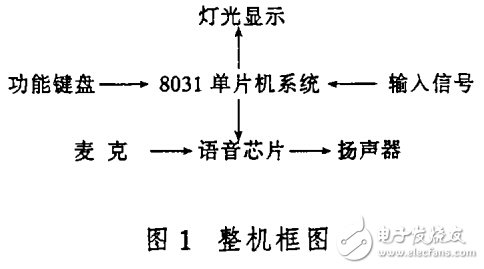
The block diagram of the eight-way voice alarm is shown in Figure 1. According to its different functions, it can be divided into three parts: the light display part, the alarm control part and the voice alarm part. In the light display section, the red light signal is used as an alarm indicator to indicate which way an alarm signal appears. In the alarm control section, the 8 03 1 microcontroller is the core component that processes the input signal and generates control signals to control the recording and playback of the voice chip and the status of the light display. The function keyboard is used to provide a way for human-machine dialogue. The signal input part mainly receives the alarm signal sent by the detecting component and generates an alarm message. When the MCU receives the information, the control performs an alarm. In the voice alarm part, the voice chip s ID l o1 6A is the core component, which can realize the voice input and release. It is a high-quality recording and playback integrated single-chip solid-state voice integrated circuit developed by the US Is D company. It can easily input voice without any special equipment. It adopts DASI (Direct Analog Memory Storage) technology, and has 128K EEPROM on the chip. Under the control of c P u, voice input and release can be realized. The difference of each signal recorded is segmented by the user himself, and is not afraid of power failure.
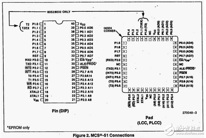
8031 pin function
(1) Main power supply pins Vss and Vcc
1 Vss ground
2 Vcc is +5 volt power supply during normal operation
(2) External crystal oscillator pins XTAL1 and XTAL2
1 XTAL1 internal oscillator circuit The input of the inverting amplifier is a pin of the external crystal. This pin is grounded when an external oscillator is used.
2 XTAL2 internal oscillator circuit output of the inverting amplifier. It is the other end of the external crystal. When an external oscillator is used, this pin is connected to an external oscillator source.
(3) Control or multiplex pins RST/VPD, ALE/, and /Vpp with other power supplies
1 RST/VPD A two-cycle high (low-to-high transition) on this pin when the oscillator is running will reset the microcontroller
During Vcc power-down, this pin can be connected to the backup power supply, and the VPD provides internal backup power to maintain the data in the internal RAM.
2 ALE/ For normal operation, the ALE function (Allow Address Latch) is provided to latch the low byte of the address to the external latch, and the ALE pin periodically emits a positive pulse at a constant frequency (of the oscillator frequency). signal. Therefore, it can be used as a clock for external output or for timing purposes. Note, however, that whenever an external data memory is accessed, an ALE pulse is skipped and the ALE terminal can drive (sink or output current) eight LSTTL circuits. For EPROM type microcontrollers, this pin receives the programming pulse (function) during EPROM programming.
3 The external program memory read strobe signal output is valid twice during each machine cycle while fetching instructions (or data) from an external program. It is also possible to drive eight LSTTL inputs.
4 /Vpp , /Vpp are internal program memory and external program memory selection. When /Vpp is high, the internal program memory is accessed, and when /Vpp is low, the external program memory is accessed.
For EPROM type microcontrollers, a 21 volt EPROM programming power supply (Vpp) is added to this pin during EPROM programming.
Hardware structure
The pin diagram of the ISD1016A voice chip is shown in Figure 3.
The circuit schematic diagram of controlling the segmented recording with a single chip microcomputer is shown in Fig. 4.
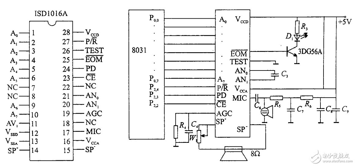
Figure 3 ISD1016A pin diagram Figure 4 ISD1016A recording and playback schematic
working principle
1 recording process
The control word is sent by the P: port of the MCU, and enters the recording waiting state. When PD=1, it immediately enters the recording state, which is the P of the MCU. The specified address of the port output starts recording. At this time, D1 emits light. When the recording is full, D1 goes out. If the CE end returns to high level during recording, the chip will automatically record the recording end address and end signal to realize segmented recording.
2 playback process
Let P / R = 1, CE = 0, enter the playback waiting state, the P0.0-P0.7 of the microcontroller to determine the starting address of the playback A0 - A7, when PD = 1, it will be from the specified address Start playing until you reach the end of the segment. During playback, the Dl light is on; the playback ends and D1 goes out.
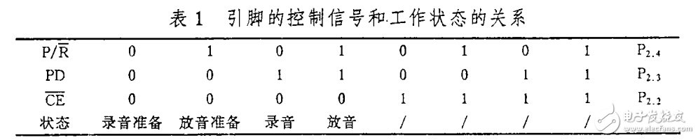
Table 1 lists the relationship between the control signals and the behavior of the pins.
Voice alarm process
After the voice content is recorded, the status selection switch is turned to the PLAY terminal, and the reset button REST is pressed, and the alarm device enters the alarm working state. At this time, the alarm device continuously queries the input alarm signal. That is to query the input signal of the PA port of 8 1 5 5 (8 0 3 1 The 1 / 0 port of the MCU itself can not meet the needs, so use 8155 to expand the 1 / 0 port), if there is an alarm at a certain time Signal, the alarm will be transferred to the alarm service program of the road to perform voice alarm, and the alarm indicator of the road will flash. At the same time, the MCU will query the ACKT key of the 8155PB port (confirmation key). If the ACKT key is not pressed, then Stop the ground alarm; when the ACKT button is pressed, the alarm stops the voice alarm and the indicator light changes to a flat light, indicating that the operator already knows where there is an alarm signal. When the fault is eliminated, press the reset button REST and restart the query, that is, work in the alarm state.
Edit Comment: The use of single-chip 8031 ​​control voice chip ISD1016A to achieve voice alarm, with strong anti-interference, small size, frequency bandwidth, signal distortion, high fidelity, low noise, high reliability, and not afraid of power failure.
Electronic enthusiast "Smart Industry Special", more quality content, download now 
T Copper Tube Terminals,Non-Insulated Pin-Shaped Naked Terminal,Copper Cable Lugs Terminals,Insulated Fork Cable Spade Terminal
Taixing Longyi Terminals Co.,Ltd. , https://www.longyiterminals.com