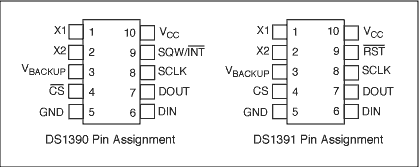
Abstract: This application note explains how to connect the DS1390 to a Motorola DSP with a built-in SPI â„¢ interface. This circuit uses the Motorola DSP56F800DEMO development board and CodeWarrior IDE.
The DS1390 real-time clock (RTC) can be connected to a microcontroller (µC) or digital signal processor (DSP) unit through an SPI interface. This application note shows how to connect the DS1390 to a Motorola DSP with a built-in SPI interface. This circuit uses the Motorola DSP56F800DEMO development board and CodeWarrior® IDE. Using the routine This routine starts with a new blank project. For details, please refer to the Motorola Toolkit Installation Guide Guide: Creating a CodeWarrior Project. The additional code for this application note is in main.c. Operation process The program controls the CS of the DS1390 through the GPIO port. The SPI controller is initialized by software, and the DSP writes the time and date to the DS1390. The software can then read the time and date cyclically. DS1390 and DS1391 support SPI Mode 1 and Mode 3.
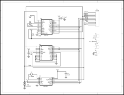
The schematic diagram is shown in Figure 1. The circuit contains a daughter card with a Motorola development board. Please note that the circuit in Figure 1 includes several RTCs with an SPI interface. Only one RTC is required at a time. This article shows that the program only supports DS1390. The program list is shown in Figure 2.

figure 1.
The DS1390 real-time clock (RTC) can be connected to a microcontroller (µC) or digital signal processor (DSP) unit through an SPI interface. This application note shows how to connect the DS1390 to a Motorola DSP with a built-in SPI interface. This circuit uses the Motorola DSP56F800DEMO development board and CodeWarrior® IDE. Using the routine This routine starts with a new blank project. For details, please refer to the Motorola Toolkit Installation Guide Guide: Creating a CodeWarrior Project. The additional code for this application note is in main.c. Operation process The program controls the CS of the DS1390 through the GPIO port. The SPI controller is initialized by software, and the DSP writes the time and date to the DS1390. The software can then read the time and date cyclically. DS1390 and DS1391 support SPI Mode 1 and Mode 3.
The schematic diagram is shown in Figure 1. The circuit contains a daughter card with a Motorola development board. Please note that the circuit in Figure 1 includes several RTCs with an SPI interface. Only one RTC is required at a time. This article shows that the program only supports DS1390. The program list is shown in Figure 2.

figure 1.

Detailed circuit diagram (PDF, 138kB)
Figure 2. Schematic of daughter card
Figure 3. Program list
Utp Connector,8P4C Connector,8P8C Crystal Head Connector,Rj45 Crystal Head Connector
Dongguan Fangbei Electronic Co.,Ltd , https://www.connectorfb.com