Characteristic data is given for these devices in both types of configuration. More recent devices, such as the DS1847, DS1848, and others, have been designed which have mechanisms internally to compensate for these changes. Consult with a Maxim FAE for the latest technology when considering a design with these types of devices as newer, improved versions are always in development.
IntroductionThe DS1845 and DS1855 are dual nonvolatile (NV) potentiometers with memory. Both devices have two linear taper potentiometers. One potentiometer has 100 positions, and the second has 256 positions. The DS1845 / 1855 can operate from a 3V or 5V supply over a temperature range of -40 ° C to + 85 ° C. A more in-depth analysis of the temperature coefficient is needed due to the different configurations possible with the potentiometers. Each configuration produces a different temperature coefficient. This application note discusses the temperature coefficient of the DS1845 / DS1855 in the voltage divider and variable resistor configurations.
Temperature CoefficientThe temperature coefficient changes depending on the device configuration. The data sheet states the end-to-end temperature coefficient is 750ppm / ° C. In voltage divider mode, the temperature coefficient is actually much lower. The temperature coefficient is lower in voltage divider mode because the temperature coefficients of each resistor branch (R1 and R2) will cancel out each other (see Figure 1). The resistance of the wiper (RW) will then primarily affect the temperature coefficient. The equations used to calculate the temperature coefficient for each mode are shown in Equations 1 and 2.
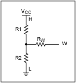
Figure 1. Resistor branches in voltage divider mode.
Voltage Divider ModeTo measure the temperature coefficient in voltage divider mode, the H terminal was tied to VCC and the L terminal was tied to ground. Using the 2-wire interface, the potentiometer position was changed and voltage was measured on the W terminal for each potentiometer position over temperature. See Figure 2 for a drawing of the DS1845 / 1855 in voltage divider mode. The equation used to calculate the temperature coefficient is below.

Equation 1.
Where,
ΔV = the difference between the voltage (V2-V1) at temperatures T2 and T1 (T2> T1), respectively
V1 = the voltage at T1
ΔT = T2-T1
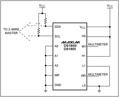
Figure 2. Voltage divider mode.
Variable Resistor ModeTo measure the temperature coefficient in variable resistor mode, the H and W terminals were tied together. The L terminal was grounded. A 1µA current was forced on the H and W terminals with the compliance set equal to VCC. Using the 2- wire interface, the potentiometer position was changed and the voltage was measured from W to ground. This measurement was repeated over temperature. Forcing a current and measuring a voltage ensures the biasing of the resistor terminal remains between VCC and ground. This ensures that the device parasitics do not affect the measurement. See Figure 3 for a diagram of the DS1845 / 1855 in variable resistor mode. The equation used to calculate the temperature coefficient is below.

Equation 2.
Where,
ΔR = the difference between the resistance (R2-R1) at temperatures T2 and T1 (T2> T1), respectively
R1 = the resistance at T1
ΔT = T2-T1
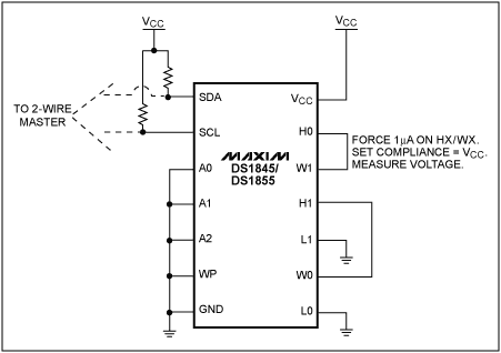
Figure 3. Variable resistor mode.
Note: Tying W to L produces the same effect.
DataNote: The results were taken on a small sample size and are not to be considered a full characterization.
Voltage Divider ModeThe temperature coefficient was calculated as approximately 10ppm / ° C using Equation 1.
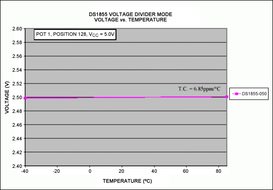
Figure 4. DS1855 in voltage divider mode (pot 1).
Figure 4 shows the voltage variation of the DS1855 in voltage divider mode over temperature. VCC was set to 5V; therefore at a 50% pot setting the voltage should be 2.5V.
The calculation below shows how the temperature coefficient for Figure 4 was calculated.

Variable Resistor ModeThe temperature coefficient was calculated to be approximately 750ppm / ° C using Equation 2.
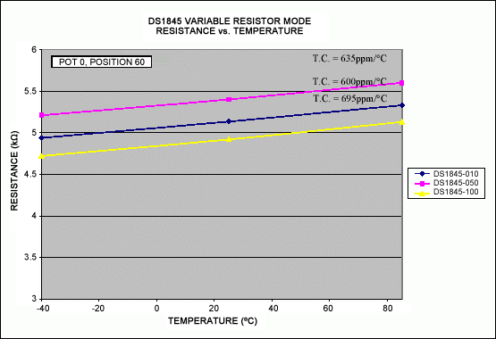
Figure 5. DS1845 in variable resistor mode (pot 0).
Figure 5 shows the change in resistance of the DS1845 in variable resistor mode over temperature. Pot 0 is a 10kΩ resistor; therefore at a 50% pot setting the resistance should be 5kΩ.
The calculation below shows how the temperature coefficient for the DS1845-050 in Figure 5 was calculated.

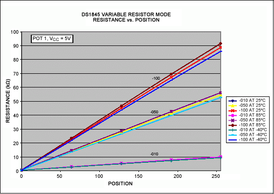
Figure 6. DS1845 in variable resistor mode (pot 1).
Figure 6 shows how the resistance changes as the pot position changes. The -100 has a 100kΩ resistor, the -050 has a 50kΩ resistor, and the -010 has a 10kΩ resistor for pot 1.
ConclusionThese results show that the temperature coefficient varies depending on the mode of the device. The results for the DS1845 and DS1855 were similar. In voltage divider mode the temperature coefficient will be on the order of 10ppm / ° C. If the device is configured in variable resistor mode, then the temperature coefficient will be on the order of 750ppm / ° C. If an application requires a variable resistor with a better temperature coefficient performance in variable resistor mode, then the DS1847 or DS1848 may provide a better solution. The DS1847 and DS1848 data sheets and app notes are located at
For any questions please contact var name = "MixedSignal.Apps @"; var domain = "dalsemi.com"; document.write ("" + name + domain + ""); MixedSignal ..
SMT Motor , original and new ,in stock, quality gaurantee.
SMT motor : actuator motor,servo motor, converyor motor,rail motor, bom stepping motor, rizing motor, Z camera motor, Y camera motor, X camera motor.
Smt Motors
Smt Juki Motors
Original Smt Servo Motor
Original Smt Motors
Holder For Smt Type
Smt Battery Holder
Smt Holder
Battery Holder
Filter For Smt Machine
High Quality Smt Filter
Smt Filter
Smt Machine Filter
Smt Tape Feeder Parts
Smt Machine Spare Parts
Original Smt Feeder
Original Smt Cable
Smt Machine Cable
Smt Spare Parts Fuji Cable
SMT Cable
Smt Belt
Smt Siemens Belt
Smt Juki Belt
Smt Conveyor Belt
Smt Camera
Smt Laser
Camera For Smt
Smt Siemens Camera
Smt Parts Plastic Rail
Smt Plastic Rail
Smt Juki Plastic Rail
Juki Plastic Rail
SMT Nozzle For Yamaha
Yamaha Nozzle
Nozzles For Yamaha Machine
Smt Yamaha Nozzle
Smt Siemens Nozzle
Smt Nozzle For Siemens
Siemens Nozzle
Smt Nozzle For Samsung
Samsung Nozzle
Smt Samsung Nozzle
Panasonic Nozzle
Smt Panasonic Nozzle
Smt Nozzle For Panasonics
Nozzles For Panasonic Machine
Smt Juki Nozzle
Nozzles For Juki Machine
Juki Nozzle
High Pressure Juki Nozzle
I-Pulse Nozzle
Nozzles For I-Pulsemachine
Smt I-Pulse Nozzle
High Pressure Fuji Nozzle
Nozzles For Fuji Machine
Fuji Nozzle
Smt Fuji Nozzle
Smt Nozzle
Smt Parts Nozzle
Smt Nozzle For Machine
Smt Spare Parts Nozzle
Yamaha Smt Feeder
Yamaha Feeder
Smt Machineyamahafeeder
Smt Feeder For Yamaha
Smt Feeder For Siemens
Smt Machine Siemens Feeder
Siemens Smt Feeder
SIEMENS Feeder
Samsung Smt Feeder
Smt Machine Samsung Feeder
SAMSUNG Feeder
Smt Feeder For Samsung
Panasonic Smt Feeder
Panasonic Feeder
Smt Machine Panasonic Feeder
SMT Feeder For Panasonic
Smt Feeder For Juki
JUKI Feeder
Juki Smt Feeder
Smt Machine Juki Feeder
I-Pulse Feeder
Smt I-Pulse Feeder
Smt Parts I-Pulse Feeder
I-Pulse Type Feeder
Pneumatic Feeder
Fuji Feeder
Smt Fuji Feeder
Fuji Smt Tape Feeder
Smt Machine Feeder
Smt Tape Feeder
Smt Feeder
Feeder For Smt Machine
Siemens Control Valves
Smt Siemens Valve
Siemens Vacuum Valve
Siemens Valves
Smt Samsung Valve
Samsung Vacuum Valve
Samsung Control Valves
SAMSUNG Valve
Juki Vacuum Valve
Juki Ejector
Juki Vacuum Ejector
Juki Valve
SMT Motor
Smt Motors,Original Smt Motors,Smt Juki Motors,Original Smt Servo Motor
Shenzhen Srisung Technology Co.,Limited , https://www.sr-smt.com