The figure below shows a schematic diagram of a compact fluorescent lamp ballast design. The ballast includes an AC input stage with an EMI filter, a passive PFC stage, a ballast control stage using the International Rectifier IR2520D adaptive ballast control IC, a half-bridge inverter and resonant output. level. Compared to existing CFL circuits, this design is improved by using a valley-filled passive PFC circuit and a lamp current crest factor control circuit to achieve higher power factor, lower total harmonic distortion (THD) and Acceptable lamp current crest factor. 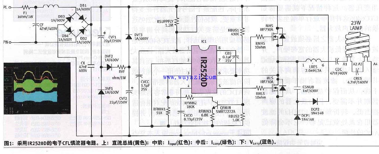
Previous: External conversion circuit when DAC0832 outputs analog voltage
Next:32W fluorescent lamp ballast circuit diagram
Related Reading EMI Filter Filter Inverter Fluorescent Lamp Ballast Lamp Ballast
- • [New product broadcast] 1N212 2016-08-10 14:18
- • [New product broadcast] 1N203 2016-08-10 14:18
- • [New product broadcast] 1N202 2016-08-10 14:18
- • [New product broadcast] 1N194A 2016-08-10 14:18
- • [New product broadcast] 1N78C 2016-08-10 14:18
- • [New product broadcast] 1N76C 2016-08-10 14:18
- • [New product broadcast] 1N58A 2016-08-10 14:18
- • [New product broadcast] 1N56A 2016-08-10 14:18
Power X (Qingdao) Energy Technology Co., Ltd. , https://www.solarpowerxx.com