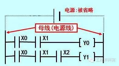
[ladder diagram]
Generally, in the program of the PLC, the direction of the current is represented in the form of a ladder diagram.
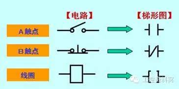
[Circuit symbol of ladder diagram]
In order to print out the various circuit contact symbols used in the PLC in the past,
Symbolize these content words and unify them into A contacts and B contacts.
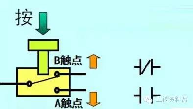
[What is A contact, B contact? 】
Example: push button switch
Turns OFF when pressed
Called B-type contact (BREAK contact) or normally closed contact, NC contact (NORMALCLOSE)
COM terminal (common terminal)
Turns ON when pressed
Called A-type contact (MAKE contact) or normally open contact, NO contact (NORMALOPEN)
ã€summary】
In many ways of PLC program. As a representative ladder mode, it is widely used because it is very similar to the relay sequence control loop.
[Ladder drawing steps]
1 draw control power bus
2Connect the contacts and input and output relays and other elements in the control power bus.
In the circuit diagram, the symbols of the timers, limit switches, relays, etc. are different, but in the ladder diagram of the PLC, there is no difference, only the text symbols that can be printed by the printer are used.
10 Mm Nano Tip,Smart Board Touch Screen Pen,Electronic White Board Pen,Infrared Touch Screen Pen
Shenzhen Ruidian Technology CO., Ltd , https://www.wisonen.com