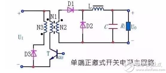
1. Single-ended forward type Single-ended: One-way drive of a pulse transformer through a switching device.
Forward: The original/paid phase relationship of the pulse transformer ensures that when the switch is turned on and the primary side of the pulse transformer is driven, the transformer supplies power to the load at the same time.
Transfer files for [membrane switch] proofing
The biggest problem of this circuit is that the switch tube T operates alternately in the on/off state. When the switch tube is turned off, the pulse transformer is in the "idle" state, in which the stored magnetic energy will be accumulated to the next cycle until the inductor The device is saturated, causing the switching device to burn out. The flux reset circuit formed by D3 and N3 in the figure provides a channel for venting excess magnetic energy.
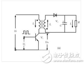
2. The single-ended flyback flyback circuit is opposite to the forward circuit. The original/paid phase relationship of the pulse transformer ensures that when the switch tube is turned on and the primary side of the pulse transformer is driven, the transformer does not supply power to the load. The original/paid side is interleaved. The problem that the magnetic energy of the pulse transformer is accumulated is easy to solve. However, due to the leakage inductance of the transformer, a voltage spike will be formed on the primary side, which may break through the switching device. A voltage clamping circuit is needed to protect the circuit formed by D3 and N3. From the circuit schematic diagram, the flyback type is very similar to the forward type. On the surface, it is only the difference between the same name of the transformer, but the circuit works differently, and the functions of D3 and N3 are different.
Transfer files for [membrane switch] proofing
3. Push-pull (transformer center tap) This circuit structure is characterized by: symmetrical structure, the primary side of the pulse transformer is two symmetrical coils, the two switch tubes are connected in a symmetrical relationship, the wheel is broken, and the working process is similar to linear A class B push-pull power amplifier in an amplifying circuit.
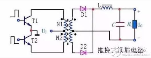
Main advantages: high frequency transformer core utilization (compared to single-ended circuit), high power supply voltage utilization (compared to the half-bridge circuit to be described later), large output power, low voltage of both bases Flat, the drive circuit is simple.
The main disadvantages are: low utilization of the transformer windings and high requirements on the withstand voltage of the switching tubes (at least twice the supply voltage).
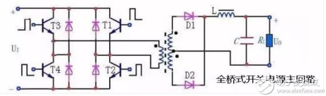
4. Full-bridge type This circuit structure is characterized in that four identical switching tubes are connected into a bridge structure to drive the primary side of the pulse transformer.
Transfer files for [membrane switch] proofing
In the figure, T1 and T4 are a pair, driven by the same group of signals, and simultaneously turned on/off; T2 and T3 are another pair, driven by another group of signals, and simultaneously turned on/off. Two pairs of switch tube wheels are turned on/off, and a positive/negative alternating pulse current is formed in the primary coil of the transformer.
Main advantages: Compared with the push-pull structure, the primary winding is reduced by half, and the switching tube withstand voltage is reduced by half.
The main disadvantages are: the number of switching tubes used is large, and the parameters are required to be consistent, the driving circuit is complicated, and it is difficult to achieve synchronization. This circuit structure is usually used in ultra-high power switching power supply circuits above 1KW.
5. The structure of the half-bridge circuit is similar to the full-bridge type, except that two of the switch tubes (T3, T4) are replaced by two equal-value capacitors C1 and C2.
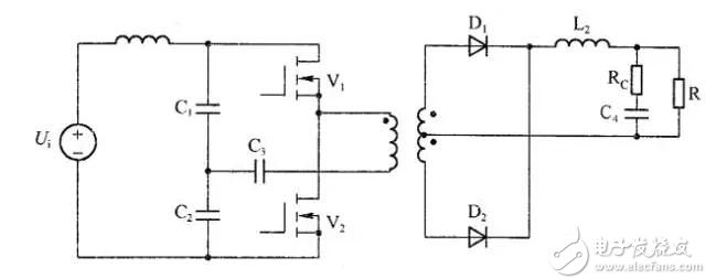
The main advantage:
Has a certain anti-unbalance ability, the circuit symmetry requirements are not very strict;
Adaptable power range is large, from tens of watts to kilowatts;
Switching tube with low pressure requirements;
Circuit cost is lower than full-bridge circuits.
Such circuits are often used in various unregulated output DC converters, such as electronic fluorescent lamp drive circuits.
58 thermal receipt printer is a high-speed, long-life, high-quality receipt printer, using direct line thermal. And suitable for various software, novel appearance design, simple operation â— High speed, long life, high quality, low repair rate, suitable for various software â— Novel appearance design, simple operation â— Support download Logo trademark printing â— Standard GB2312 Chinese character library supports Simplified/Traditional and multiple international languages â— 100MB Ethernet interface, connect, print faster, avoid lost orders
58Mm Thermal Printer ,Thermal Printer For Shipping Labels,Thermal Transfer Printer,Wireless Thermal Printer
ShengXiaoBang(GZ) Material Union Technology Co.Ltd , https://www.sxbgz.com