For existing wireless local area network (WLAN) devices and chipset manufacturers, the recently approved draft 802.11n standard is a catalyst for a new market. When this standard is fully developed, these companies will be able to achieve better performance with a large number of wireless Internet access products and create a new audio and video distribution (distribuTIon) market. However, the implementation of megaTIple input and mulTIple output (MIMO) radio frequency capability is contrary to the current trend of shrinking product size, power consumption and cost reduction. This article will discuss the challenges of designing an RF MIMO solution; summarize key performance indicators and explain how MIMO front-end modules can help product developers solve these design challenges.
The advantages of 802.11nCompared with existing wireless data standards, 802.11n has several advantages. With a data rate of 200 to 400 Mbps, 802.11n provides a wide enough data channel for home networking and downloads, as well as media distribuTIon. In addition, the standard has two advantages (although both are often overlooked because of the higher speed), which is a 20% to 30% increase in frequency range over the existing 802.11a/b/g standard. And has backward compatibility with 802.11a/b/g. Backward compatibility allows users to use the same devices in home, office, and travel applications (although data rates and frequency ranges may be smaller than full MIMO solutions). 802.11n client cards use 802.11n wherever possible; and return to the 802.11a/b/g standard at existing hotspots. Compared to other competing solutions, the ultimate advantage of 802.11n is that it uses the same spectrum as the 802 a/b/g standard, both 2.4 and 5 GHz. This allows manufacturers to fully enjoy the economies of scales of existing process technologies, components and suppliers, making high-speed networks less expensive.
Technical challenges of RF designThe Error Vector Magnitude (EVM) is very important for total throughput and performance. A complete front-end module should have less than 3% (-30 dB) of distributed EVM (contributed EVM) at rated output power. In MIMO, better linearity is required. why? Because you want to extract the channel model, you need to have a very good transmitter. If the EVM used as the transmitter for channel model extraction is poor, the performance of MIMO will be greatly reduced. However, the EVM standard alone is not enough. The EVM feature of the front-end module should be as close as possible to the exponential curve shown in Figure 1a, rather than having a "sweet spot" like Figure 1b. The characteristic curve in Figure 1b has an optimum point of 1 or 2 dB, and the power amplifier (PA) must operate at this point to provide the specified performance. Above or below the optimal point, the working front-end module generates additional EVM and reduces throughput. The main problem here is that the optimum point drifts with process, voltage, matching circuitry, and temperature, so the EVM allocation increases and throughput decreases. Front-end modules with this type of performance will be difficult to apply to products that require minimum performance standards.
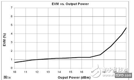
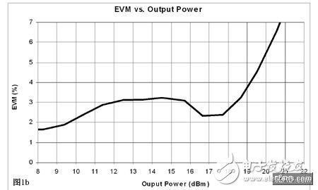
In addition, a front-end module with exponential EVM features allows you to use the same design around the world when different regions have different regulatory standards for output power limits. The design is targeted at the area with the highest output power, and when the design is used in other areas, its performance can be improved. However, this is not the case for front-end modules with the EVM feature shown in Figure 1b.
For MIMO, the exponential EVM feature offers similar advantages. Some regulations define this power as the total power of all antennas. Therefore, even if the front-end module can provide a large output power for each antenna, the output power may need to compensate 3-6 dB to meet the regulatory requirements. However, in the same product, if a single antenna of the original 802.11 a/b/g standard is used, the user wants to transmit at the highest output power. As discussed above, operating under the different power levels with the characteristics of Figure 1b will cause performance degradation.
DimensionsAs standard product sizes shrink, wireless standards become more complex and require more circuitry and higher power consumption, which is an extreme challenge for RF designers.
The latest form factor PCIE mini card is only half the size of the mini PCI card that currently dominates the WLAN market. Mini PCI cards are widely used in notebook computers, personal computers, and access points. These existing designs use only one RF transmit link and one RF receive link; however, MIMO 802.11n applications require two RF transmit links and two RF receive links, as shown in Figure 2. Considering the number of components, plus the keep out areas that are set up for production needs, it is extremely challenging to implement these circuits in the size of the PCIE Mini Card. However, this is the real advantage of the MIMO front-end module: a fully tested single RF solution that integrates all the circuitry needed to output from the transceiver to the antenna.
To compare the integration of front-end modules, it is important to perform strict simulations. Sometimes, functionality is masked by the power of RF functionality (output power, EVM), but it is important for cost and critical board space.
Control interface: Is the control interface CMOS? If not, additional circuitry will be required to connect the front-end modules to the IC.
Bias voltage: Does the front-end module require a bias voltage? If desired, an external regulator is often required to provide a bias voltage typically ranging between 2.7 and 2.9V, and an additional transistor circuit is used to initiate or disable the bias voltage. In addition to size and cost, the performance of the front-end module (FEM) is directly related to the bias voltage, which varies with temperature and voltage.
Current consumptionAlthough developers may think that current consumption and form factor are not related, in fact, two of the three problems caused by front-end module current consumption are directly related to the form factor.
Current consumption has been associated with battery life. Product developers want the highest power at the lowest current consumption, and sometimes even the willingness to accept a slightly lower output power in exchange for a 10% longer battery life. The same problem exists in MIMO applications, but the situation is even worse, as there are two complete transmit links working in these applications simultaneously. This means that front-end module vendors must develop more efficient, lower current consumption modules to meet the needs of the MIMO market. This will become even more critical if MIMO enters smaller embedded applications such as PDAs, mobile phones and game consoles.
While battery life is important, another, more important reason for developing an efficient front-end module is that the form factor standard clearly defines how much power is available to the PCI card. Under the original 802.11 a/b/g standard, the current consumed by these cards is far from the limits of these specifications. However, as process technology continues to increase and MIMO systems have multiple channels, the current consumed by the PCI card may be close to or even exceed the limits specified by the form factor standard. Since PA is generally the most current-consuming device, front-end module vendors are under greater pressure to advance technology and physics to achieve efficient solutions.
Front end moduleFront-end module manufacturers who also design components such as PAs and switches can use techniques to optimize matching and biasing to minimize losses in the transmit-receive link. In addition, they can take advantage of new technologies to achieve high levels of integration to achieve this small form factor. These technologies are not available in the components currently visible on the market.
With a fully tested solution that meets high output power, low EVM and low current consumption requirements, a single front-end module can solve all of the system problems discussed above and help developers speed time to market. Because this front-end module is a fully tested solution that can replace about 60 components, the yield of end products will increase. A single front-end module has a greater advantage than using multiple front-end modules with lower integration, because each component has its no-wiring area, and the more components you need to occupy the board area. In addition, in general, the pins of these front-end modules are mirrored to the transceiver interface, thus limiting the economies of scale that the device can provide.
Many people do not know what kind of cameras are invisible cameras, and do not know how to distinguish invisible cameras, so here is how to distinguish invisible cameras.
Invisibility, as the name suggests, means that it is not easy to be seen or found, so where do such cameras exist? In fact, invisible things are hidden by the external environment, so they will not be discovered. Such invisible cameras are generally hidden in things that are more difficult to see, such as: inside the socket, inside the TV, inside the stereo, inside the fan, etc. Cameras can be hidden in various household appliances. Why should they be hidden in electrical equipment? The main reason is that these equipments have power supply and will not be used because the camera cannot be powered.
Camera Pen,the memory reaches 32G,easy to carry camera,Hidden Camera HD1080p,Hidden Camera HD720P
Jingjiang Gisen Technology Co.,Ltd , https://www.gisengroup.com