The waveguide coupler has a large number of applications due to low insertion loss, high power, high directivity microwave communications, test measurements, and the like. At the same time, because of its three-dimensional structure, the waveguide coupler has a variety of coupling modes (broad-side/narrow-side/multi-way/parallel/cross-coupling). Among them, a very widely used structure is a Bezi hole coupler (also called pinhole coupling). ), Bates porous coupler follows the branch line bridge principle. Here is a Vband (65G ~ 75G) porous coupler design ideas.
1. Principle analysis of branch line bridgeBranch line bridge theory to explain better books personally recommend "modern microwave filter structure and design," the contents of Chapter 15 of the next volume, branch line bridge as a symmetrical four-port network is also suitable for odd-even mode analysis, see the schematic diagram 1 As shown. (For details, refer to section 15.8 of this book.)
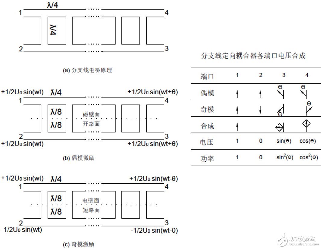
Figure 1, principle of branch line bridge
For even-mode excitation, the symmetry plane of the branch line bridge can be regarded as a magnetic wall as shown in Fig. 1(b), half of which is analyzed (the other half is identical), and the circuit can be seen as an open circuit with a 1/8 wavelength branch. Stab line, and each stab line is separated by 1/4 wavelength. The voltage will shift phase θ through such a circuit.
Similarly, for odd-mode feeds, the circuit can be thought of as a short-circuit stub with a 1/8-wavelength stub, and the stab lines are separated by 1/4 wavelength. Voltage through this circuit will phase -θ.
The first important conclusion is: The power after odd-even mode superposition:
· 1 is 1
· 2 ports are 0 (isolated)
· 3 ports are sin(θ)^2
· 4 ports are cos(θ)^2
• The 4 and 3 outputs are 90° out of phase at the center frequency and are 90° directional couplers.
(If θ=45°, the bridge is a 3 dB bridge. If θ=30°, the bridge is a 6 dB bridge, so the coupling degree can be represented by an angle. Here you can also take a look at the phase shift. Knowledge
2. Superposition principle of branch line bridge
If several matched directional couplers are cascaded, then their cascade effect acts like a directional coupler, and the cascaded response follows the angle superposition principle (coupled linear couplers also comply with this principle). For example, a 3 dB bridge is 45°. We can cascade two 22.5 degree bridges. A 22.5° bridge coupling ratio = 20*log(sin22.5)=-8.343dB. This is also 8343. The reason for the popularity of couplers.
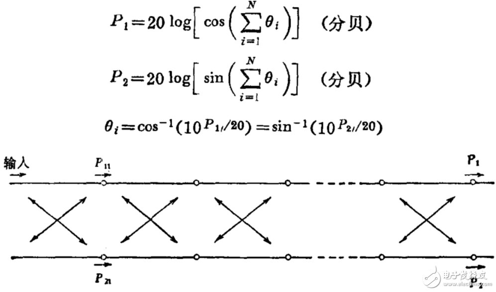
Figure 2. Superimposed schematic of a bridge or coupler
3, branch line bridge ADS principle simulationThe aperture coupler obeys the branch line bridge principle. We establish the branch line bridge model in ADS and obtain the coupling degree of each level of small holes. The schematic diagram is shown in Figure 3. After a simple optimization, we can obtain the ideal branch impedance. Because the branch line bridge meets the principle of superposition, we can calculate the degree of coupling provided by each branch line, and then the design of the porous coupler becomes a single-hole coupler design.
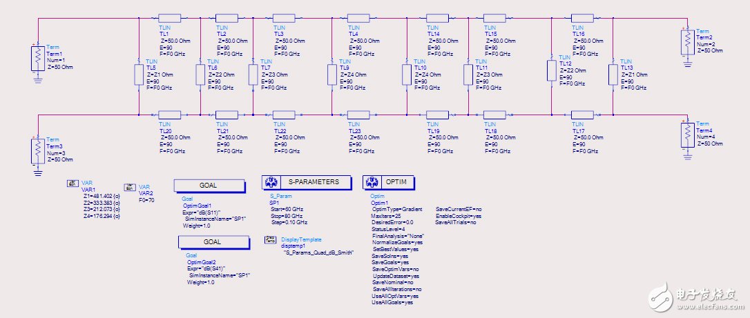
Figure 3. Modeling of branch bridges in ADS
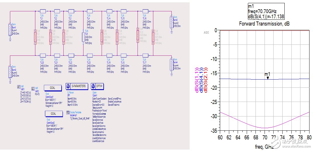
Fig. 4. Determination method of single branch coupling degree
Through the operation of Fig. 4, the branching sections are sequentially enabled, and the contribution value of each branch to the coupling degree can be determined. Thus, we turn the porous problem into a single-hole coupling problem. For example, the fourth node in Figure 4 provides -17dB coupling. We only need to find a -17dB coupling hole in the 3D simulation.
4, three-dimensional simulation of the couplerThrough the principle of simulation in ADS we can determine the coupling degree of each section, so that we convert the porous problem into a single hole problem. The three-dimensional simulation of the coupler becomes a two-step coupling of single-hole coupled data acquisition and porous cascade joint defense.
· Determination of single hole coupling
Two parallel waveguides will generate coupling if there is only one small hole, and the coupling hole has a variety of forms. Here, a two-hole coupling is used as an example. Other coupling modes can be felt by themselves according to the steps in this paper.
The model shown in Fig. 5 is established in the HFSS. The wall thickness between the two waveguides is as thin as possible according to the machining constraints. Here, 0.4 mm is taken. The corresponding coupling degree is obtained by scanning the size of the coupling hole. The waveguide size of Vband is: a = 3.1mm, b = 1.55mm, and the wall thickness between the two holes is at least 0.4mm, then the maximum coupling hole radius is taken as 0.65mm, and the minimum is taken as 0.25mm (bit limit).
Through the small hole diameter scanning, it can be seen that the two small holes can provide a maximum coupling of -29.5 dB, which is far lower than the maximum coupling required in the ADS simulation. (In general, we must first estimate the maximum and minimum coupling quantities that each coupling can provide, and then model in ADS.) Through this step, we determine the upper and lower limits of the amount of coupling that small holes can achieve. This can be returned to ADS for re-modeling. simulation. (Note that the phase difference between the coupling path and the straight path must also be guaranteed to be 90°)
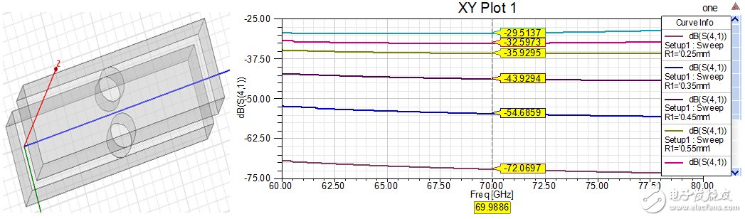
Figure 5. Two-hole single-cell coupling in HFSS
· Porous Coupler 3D Simulation
Since the maximum coupling amount provided by the small hole is -29.5 dB, the coupling amount is very small, and it is not returned to the simulation in the ADS. A single-section coupler of -29.5 dB is directly used for multi-stage cascading to achieve 3 dB coupling.
By calculation, the angle of -29.5° is 1.92°. To achieve 45°, it can be achieved by 45/1.92=23 knots. A coupler of 23 sections is established in the HFSS, with a coupling degree of -29.5 dB per coupler and a coupling hole pitch of 1/4 wavelength (1/4 wavelength self-calculating). The result of one calculation is shown in Figure 6. It can be seen that our rough estimate is also very good.
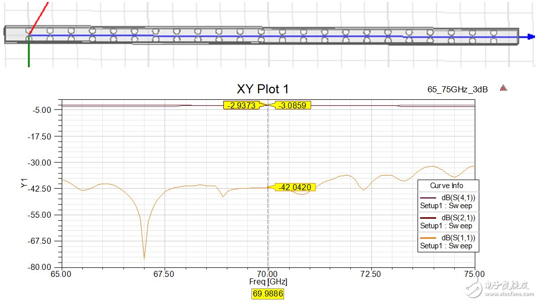
Figure 6. Vband porous coupler simulation results
In the actual product, due to the loss, the coupling degree is not necessarily exactly -3dB, and it needs to be corrected by actual debugging.
The smaller the degree of coupling of the branches in the branch line bridge is, the wider the bridge can be, but when the coupling amount of -20 dB is seen in the ADS schematic, the impedance of the branch line has reached 200 ohms. Such an impedance It is very difficult to realize in the microstrip, which is why the broadband micro-band bridge cannot use the branch line method, and the broadband phase shifter is also very difficult to achieve.
Product introduction
1000kVA and above Oil Immersed Transformers must be equipped with outdoor signal thermometers and can be connected to remote signals. Oil immersed transformers of 800kVA and above shall be equipped with gas relay and pressure protection device. Oil immersed transformers of 800kVA and below can also be equipped with gas relay according to the use requirements and through consultation with the manufacturer. Dry type transformers shall be equipped with temperature measuring devices according to the manufacturer's regulations, generally 630kVA and above transformers.
According to the phase number of a single transformer, it can be divided into three-phase transformer and single-phase transformer. In three-phase power systems, three-phase transformers are generally used. When the capacity is too large and limited by transportation conditions, three single-phase transformers can also be used to form a transformer bank in three-phase power systems.
According to the number of windings, it can be divided into two winding transformers and three winding transformers. Generally, transformers are double winding transformers, that is, there are two windings on the iron core, one is the primary winding and the other is the secondary winding. The three winding transformer is a transformer with large capacity (above 5600 KVA), which is used to connect three different voltage transmission lines. In special cases, there are also transformers with more windings.
According to the structure, it can be divided into core type transformer and shell type transformer. If the winding is wrapped around the iron core, it is an iron core transformer; If the iron core is wrapped around the winding, it is a shell type transformer. However, they are slightly different in structure and have no essential difference in principle. All power transformers are iron core type.
According to insulation and cooling conditions, it can be divided into oil immersed transformer and Dry Type Transformer. In order to strengthen the insulation and cooling conditions, the core and winding of the transformer are immersed together in the oil tank filled with transformer oil. In special cases, such as street lamps and mine lighting, dry-type transformers are also used.
In addition, there are various special transformers for special purposes. For example, high-voltage transformer for test, transformer for electric furnace, transformer for electric welding and transformer for SCR circuit, voltage transformer and current transformer for measuring instrument.
Conservator Type Transformer,5000Kva Transformer,66KV Transformer,33Kv Transformer,High voltage transformer
Henan New Electric Power Co.,Ltd. , https://www.newelectricpower.com