Power splitters are used in a wide range of microwave circuits, especially in phased-array/solid-state power synthesis. Today, almost every microwave product has its presence. In many professional books, there are introductions of power splitters. Individuals highly praise the book “Microstrip Circuits†edited by Tsinghua University. Reading this book can feel the rigorous style of the pioneers of the old generation of microwave circuits. Actually, it is very helpful to enhance the design of microwave circuits because it is detailed but easy to understand.
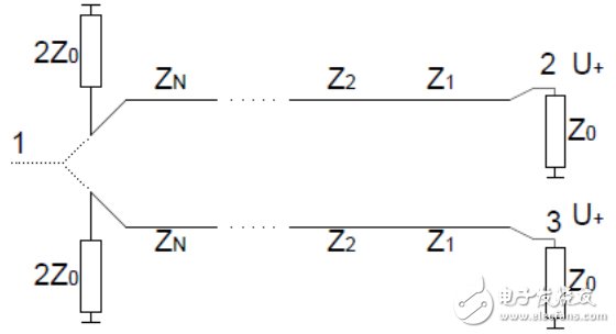
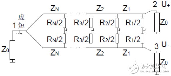
1. The core view of the power dividerThe detailed theoretical derivation can be found in Chapter 6 of the "Microstrip Circuit". Here only the core conclusions in this book are quoted. It is also strongly recommended to read this chapter carefully. The methodology inside is a magic weapon to solve many microwave circuit problems. The splitter can be split into two odd-mode and even-mode two-port networks based on symmetry. The schematic is shown in Figure 1.
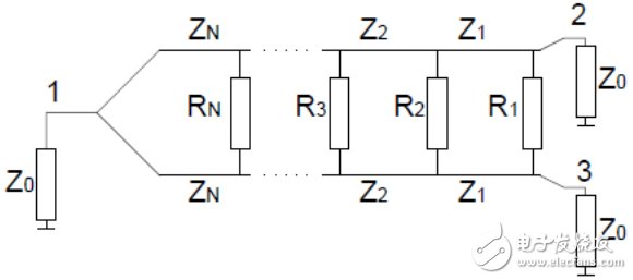
(a) N-bandwidth band splitter
(b) Even-mode feed equivalent circuit
(c) Odd-mode feed equivalent circuit
Figure 1, the theoretical analysis of the power divider
The core conclusions are:
· For the common 1 port, the odd-mode feed has no effect on it. As long as the even-mode circuit is analyzed, the 1-port echo and the even-mode circuit 1-port echo are equal. The transmission line design of the power splitter thus becomes a design of a 2*Zo to Zoo impedance transformer.
· The even-mode feed circuit is also the working principle of the power combiner. 2-port and 3-port inputs are of the same amplitude and can be transmitted to 1 port without loss. Some people often confuse that S21 = -3dB, based on the reciprocity of the passive circuit S12 = -3dB, so there is no way to achieve power doubled. This situation occurs when there are only two input signals and three have no signal input.
· From the odd-mode circuit, the pure odd-mode feed feed has no power. The isolation resistor purely acts as an attenuator/load and completely absorbs the power of the odd-mode feed, achieving a low standing wave and high isolation of the 2 and 3 ports.
2, the simulation design of the power dividerAccording to the previous theoretical analysis, a splitter design actually becomes an impedance transformer design. There are many ways to implement an impedance transformer: step impedance transformer/transformer/impedance transform filter can be realized. The most commonly contacted is a stepped impedance transformer, but in practice, the power dividers of the transformer and impedance transform filter structures have very good results in many special scenarios.
The following uses a 2-18 GHz power splitter to introduce the detailed design process. Plate selection rogers5880 t=0.254mm.
1) Design steps
Impedance converter order and impedance confirmation
· Isolation resistor resistance verification
· Individual impedance transformer electromagnetic simulation
· T-shaped electromagnetic simulation
· Whole power splitter combined with electromagnetic simulation
2) Impedance Converter Order and Parameter Acquisition
There are many small softwares for obtaining the order and parameters of the impedance converter. Here, the corresponding parameters are obtained by modeling and simulating in the ADS. The model is shown in Fig. 2, in which the effective dielectric constant can be obtained through the transmission line calculation tool, and the initial value of the initial value is the center frequency. The 1/4 wavelength, other impedance values ​​are arranged from high to low, and after simple optimization, the impedance at each level can be obtained.
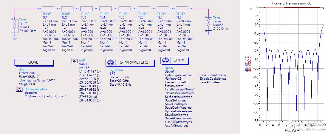
Figure 2. Impedance converter model and results in ADS
The actual width of each impedance can be calculated by the transmission line calculation tool (ADS comes with or polar si9000) as shown in Table 1. (Plate rogers 5880 Er=2.2 t=0.254mm)
Table 1, impedance and line width correspondence table
Z1Z2Z3Z4Z5Z6Z7Z8Zo
Impedance 91.786.18073.867.962.658.254.650
Line width 0.230.270.320.370.440.510.580.640.74
3) Isolation resistance simulation
According to the results of the second step, a complete theoretical model of the power divider is established in the ADS. The parameters of the transmission line are fixed, and the isolation resistor is added. An initial value is given arbitrarily. The isolation resistance can be easily obtained by a 2-port standing wave optimization. Numerical value. The circuit optimization results are shown in Figure 3.
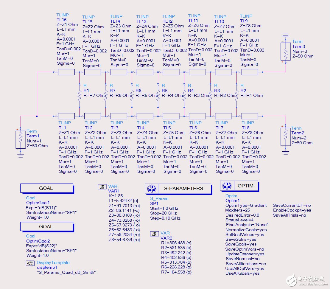
Figure 3. The complete power divider theoretical model
4) Electromagnetic simulation of impedance transformers and T-sections
According to the parameters calculated above, electromagnetic simulation can be performed. Personal habits can be simulated in sonnet. A typical power divider circuit is shown in Figure 4. Direct simulation of this circuit results in a longer simulation time for the model. Here, we split it into two separate simulations to optimize and reduce resource consumption, and then perform a joint simulation verification.
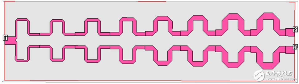
Figure 4. Typical splitter circuit
The two circuits that are decomposed are a 100 to 50 ohm impedance transformer and 50 to two 100 ohm T-junctions.
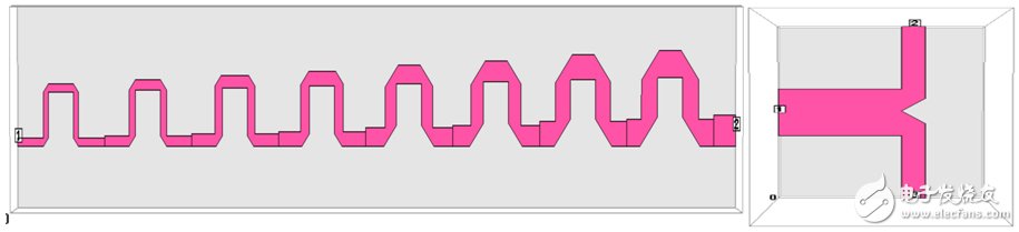
Figure 5. Two splitter circuits of the power divider
According to the size of the impedance transformer calculated in step 2), the impedance transformer model of FIG. 5 is established (the bending process is performed to reduce the length, and the bending and cutting angle can be calculated by itself). The simulation results obtained without any optimization are shown in Figure 6, which shows that the parameters calculated in the ADS model are very accurate.
The simulation results of the T-section are shown in Fig. 6. Since I built the model, I cut corners at the T-section based on experience. The results of a T-section simulation are also better. Actual design may need to adjust the size of the T-section cut-off angle, please feel free to yourself.
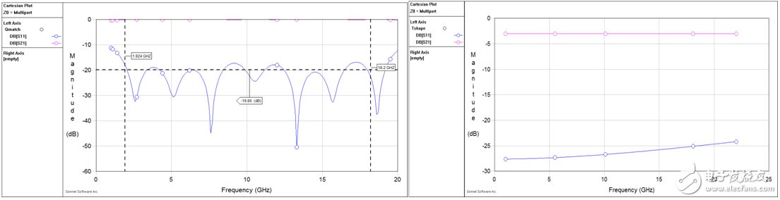
Figure 6. Simulation results of impedance transformer and T-section
5) Overall simulation of splitter model
The overall simulation of the power divider is to combine the impedance transformer and the T-section into the overall power divider of Fig. 4. Here, we introduce the netlist circuit simulation of Sonnet. A new netlist circuit in the sonnet is shown in Figure 7. This is actually a simulation that combines the sub-circuits of step 4). Other large-scale circuits can be divided into small circuits in this way and then use netlist to combine the sub-circuits, which can speed up the simulation and optimization. The comparison between the Netlist circuit simulation result and the full circuit simulation result is shown in FIG. 7 , and the correctness of the circuit segmentation and the accuracy of the entire power divider circuit simulation process can be seen. After the resistance is brought in, the entire power divider is basically simulated.
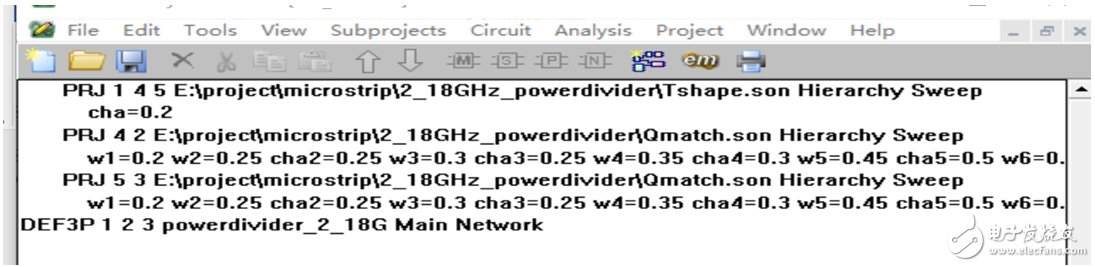
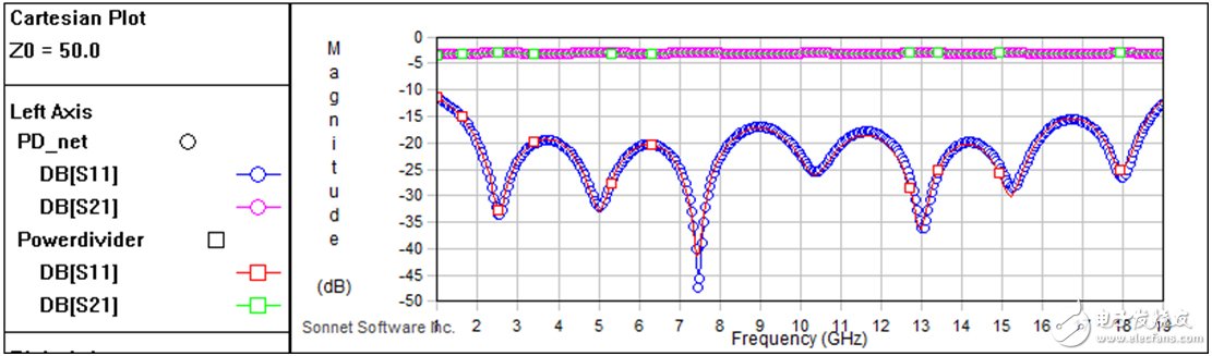
Figure 7. Comparison of netlist circuit simulation and full circuit simulation results
Pc Power Supply,Gold Pc Power Supply,Desktop Power Supply 650W,Psu Computer Power
Boluo Xurong Electronics Co., Ltd. , https://www.greenleaf-pc.com