The traditional attitude measurement system uses the Strapdown Inertial Navigation System (SINS), which has a relatively small volume, relatively low cost, easy installation and maintenance, and higher reliability than the platform inertial navigation system. Therefore, the Strapdown Inertial Navigation System has been widely studied and applied in aircraft navigation and attitude measurement.
However, the traditional attitude measurement system including the strapdown inertial navigation generally has the characteristics of large volume, heavy weight and high complexity, which makes the traditional attitude measurement system not applicable to daily applications. At the same time, the traditional strapdown inertial navigation system generally needs the assistance of a north-seeking system to obtain the azimuth of the carrier, but the traditional north-seeking system is mostly a gyro-based system, and its volume and complexity are also unacceptable for everyday applications. It can be seen that for embedded systems with strict limits on volume, a small attitude measurement system needs to be developed to meet the requirements of attitude measurement. The rapid development of MEMS technology and MR technology has made it possible to develop such a low-cost, small-volume, highly integrated attitude measurement system, which enables the ability to measure attitudes in volume- and cost-sensitive systems.
This paper discusses an attitude measurement system consisting of a MEMS accelerometer and an MR sensor. In this system, a three-axis MEMS accelerometer is used to obtain the pitch angle and roll angle of the carrier based on the gravity vector, and the output of the three-axis MR sensor can be given a matrix after matrix transformation with the pitch angle and the roll angle as parameters. Azimuth relative to the geomagnetic North Pole.
2. Hardware Description:The attitude measurement system discussed in this paper is mainly composed of a three-axis MEMS accelerometer, a three-axis MR sensor, an ARM core microcontroller and an LCD display for displaying results.
2.1 three-axis MR sensor
This system uses Honeywell's HMC2003 triaxial magnetoresistive sensor. The HMC2003 is a high sensitivity triaxial MR sensor that is a combination of a single axis MR sensor HMC1001 and a dual axis MR sensor HMC1002. Its accuracy can reach 400ugauss, the range is ±2gauss, and the sensitivity is 1V/gauss. The magnetoresistive sensor will be magnetized after experiencing a strong magnetic field, causing hysteresis, which will cause distortion of the output signal. Honeywell's “set/reset†function can Eliminate this hysteresis and return the sensor to normal operation.
2.2 Three-axis MEMS accelerometer
The accelerometer in this system uses Freescale's MMA7260Q single-chip three-axis accelerometer. The MMA7260Q is a low-cost capacitive micromechanical accelerometer with internal signal conditioning, single-pole low-pass filter, temperature compensation, etc. The range can be programmed to select one of 1.5g/2g/4g/6g. Its main features are as follows:
2.3 microprocessor
The microprocessor selected for this system is Atmel's At91sam7s64 ARM microcontroller. The At91sam7s64 is a low-pin-count high-performance microcontroller with a built-in Flash based on a 32-bit ARM core. It integrates 64k bytes of Flash and 16k bytes of SRAM and a large number of peripheral interfaces, such as two USART interfaces, which can be used to communicate with the PC and control the serial LCD display to display measurement results. It has a 10-bit SAR successive approximation A/D converter with an 8-to-1 analog multiplexer. The sampling rate of the A/D converter can reach 384ksps. The maximum operating frequency of the At91sam7s64 ARM core can reach 55MHz, 0.9Mips/MHz. The above features make the At91sam7s64 ideal for low-cost volume-sensitive attitude measurement systems.
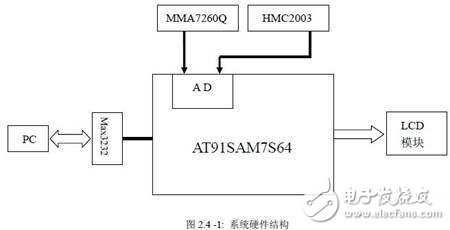
2.4 hardware structure:
The hardware structure of this system is shown in Figure 2.4-1. Because the At91sam7s64 has an on-chip A/D converter and an 8-to-1 analog multiplexer, the MMA7620Q and HMC2003 can be directly connected to the microcontroller without the need for an A/D converter and multiplexer, which not only reduces system cost and The volume increases the integration of the system while reducing the error source and improving the accuracy. After the A/D conversion measurement data is processed by the ARM core, it is sent to the serial port LCD and sent to the PC through the RS232 interface for further analysis.
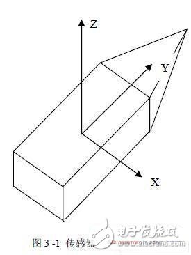
In this system, the three-axis accelerometer and the three-axis MR sensor are mounted on the board in the following manner: their X-axis is parallel to the horizontal axis of the system and the Y-axis is parallel to the longitudinal axis of the system, X The Y and Z axes are defined as the right hand coordinate system, as shown in Figure 3-1.
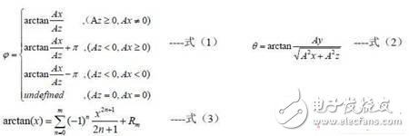
3.1 Obtaining the pitch angle and the roll angle:
In order to obtain the elevation angle θ and the roll angle φ of the system based on the gravity vector, three outputs of the accelerometer are required: Ax, Ay, Az. The pitch angle and the roll angle can be calculated by the following formulas (1) and (2). get. For the microcontroller, the arctan(x) in the function needs to be expanded by Taylor of the following formula (3) before it can be calculated.
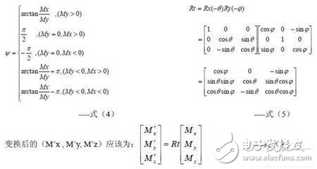
3.2 Azimuth acquisition:
In order to obtain the azimuth of the system relative to the local geomagnetic vector, it is necessary to use the three outputs of the MR sensor Mx, My, Mz. When the system is placed in a horizontal state (the pitch angle and the roll angle are both 0), the azimuth angle can be It is given directly by equation (4), but in most cases, the system does not work in a horizontal state, in which case the vertical component of the earth's magnetic field will affect the values ​​of Mx and My, so it cannot be directly obtained by equation (4). Azimuth relative to the geomagnetic vector. In order to obtain the correct azimuth in all cases, the pitch and roll angles must be taken into account, ie the coordinates must be measured by the pitch and roll angle parameters (Mx, My, The Mz) vector is transformed into a vector (M'x, M'y, M'z) in a horizontal coordinate system having the same azimuth angle as the carrier coordinate system, and its transformation matrix is ​​as shown in the formula (5).

So far, the three attitude parameters of the system are all given by equations (1)(2)(7).
The military Wire Harness is an industry applied in the military, and the arms industry is a powerful industrial sector.
In China, the military industry mainly refers to the industrial departments and factories and other military units that mainly serve the national defense construction and directly provide weapons and equipment and other military supplies to the troops. Weapons products mainly include the weapons industry, aviation industry, shipbuilding industry, electronics industry, nuclear industry, aerospace industry, etc. The main products are guns, ammunition, tanks, military vehicles, military aircraft, military ships, military electronic equipment, rockets, missiles, military aerospace equipment, nuclear weapons and military clothing.
Typical requirements for military wire harnesses:
Excellent optical performance;
Strong connections to withstand shock and vibration;
Operating temperature range from -55°C to +125°C and beyond;
Lightweight design and compact size;
Combining high density and high channel count;
Low sensitivity to corrosion, pressure and humidity.
With our diverse capabilities and certifications, Kable-X is proud to be a top military Cable Assembly manufacturer. Kable-X's robust quality assurance process ensures that we meet all documentation requirements, product configuration and verification requirements. All finished cable assemblies have undergone strict continuity, resistance, mechanical integrity and withstand voltage electrical tests to ensure reliability and performance under any conditions.

Military Wire Harness,Military Cable Assembly,Wire Harness Specialist,Mil Spec Wire Harness
Kable-X Technology (Suzhou) Co., Ltd , https://www.kable-x-tech.com