The EIA-RS-232C specifies the electrical characteristics, logic levels, and various signal line functions.
On TxD and RxD:
Logic 1 (MARK) = -3V to -15V
Logic 0 (SPACE) = +3 to +15V
On control lines such as RTS, CTS, DSR, DTR, and DCD:
Signal is valid (ON, ON state, positive voltage) = +3V to +15V
Invalid signal (disconnected, OFF state, negative voltage) = -3V to -15V
The above provisions explain the definition of logic levels in the RS-232C standard. For data (information code): The level of the logic "1" (pass mark) is lower than -3V, the level of the logic "0" (space) is higher than +3V; for the control signal; the ON state (ON) The effective signal level is higher than +3V, and the off-state (OFF), that is, the signal-invalid level is lower than -3V. That is, when the absolute value of the transmission level is greater than 3V, the circuit can be effectively checked. The voltage between 3 and +3V is meaningless. The voltage below -15V or above +15V is also considered meaningless. Therefore, during actual operation, the level must be between -3V to -15V or +3V to +15V. between.
EIA RS-232C and TTL conversion: EIA RS-232C uses positive and negative voltages to represent logic states, which is different from the TTL logic states that logic states are high and low. Therefore, in order to be able to connect to a computer interface or a terminal TTL device, the level and logic relationship must be changed between the EIA RS-232C and the TTL circuit. The method to achieve this transformation can be discrete components, and integrated circuit chips can also be used. Currently more widely used integrated circuit conversion devices, such as MC1488, SN75150 chip can complete the TTL level to EIA level conversion, and MC1489, SN75154 can achieve EIA level to TTL level conversion. MAX232 chip can complete TTLâ†â†’EIA bidirectional level conversion.
Rs232 defect(1) The signal level of the interface is high, the chip of the interface circuit is easily damaged, and because it is incompatible with the TTL level, it is necessary to use a level shift circuit to connect with the TTL circuit.
(2) The transmission rate is low. In asynchronous transmission, the baud rate is 20 Kbps; therefore, in the CPLD development board, the baud rate of the integrated program can only be used as 19200, which is also the reason.
(3) The interface uses a signal line and a signal return line to form a common ground transmission mode. This common ground transmission is prone to common-mode interference, and therefore has weak noise immunity.
(4) The transmission distance is limited. The maximum transmission distance standard value is 50 feet. In fact, it can only be used for about 15 meters.
RS232 typical application circuit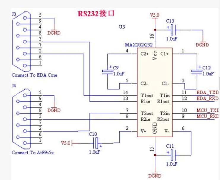
AVR series microcontrollers have asynchronous serial interfaces, and we now learn that ATmega64 has two serial ports. We know that the level of the microcontroller is generally TTL level (the difference between TTL level and other levels such as CMOS level, we later explain separately), and the computer's serial port is RS-232 level, these two levels can not Match each other, so if the two levels are interconnected, a level conversion circuit is needed. In this example, a commonly used MAX232 chip is used, which realizes the interchange of RS-232 level and TTL level.
In the data sheet of MAX232, there is a typical connection circuit of this chip, we can use this kind of circuit directly. Regarding the connection circuit of MAX232, it is actually very simple, we just need to remember 4 electric capacity (or 5 electric capacity) on it. The 4 capacitors here means that only 4 capacitors need to be connected in the circuit; as for the 5 capacitors, the extra capacitor is the capacitor between VCC and GND. This capacitor can be disconnected, but considering the stability of the power supply. Above, it is recommended to connect. As for the selection of the capacitor size in the circuit, reference can be made to the data sheet. It should be noted that non-polarity capacitors (non-positive and negative) are used here. There are three general choices of capacitance values: 0.1uF, 1uF, and 10uF. The size of the capacitor will affect the port's drive capability, large capacitance, strong drive capability, small capacitance, and weak drive capability. It is usually sufficient to use a 1uF capacitor.
The RS-232 serial communication circuit diagram is as follows:
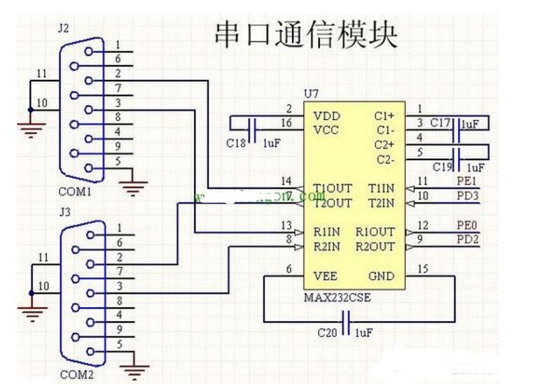
RS-232 is one of the communication interfaces on personal computers and is an asynchronous transmission standard interface defined by the Electronic Industries Association (EIA). The RS-232 interface usually appears as a 9-pin (DB-9) or 25-pin (DB-25) type, since serial communication is a one-bit transfer of information on a transmission line. The number of transmission lines is small, and information can be transmitted via the existing telephone network. Therefore, it is particularly suitable for long-distance transmission. For people-to-machine switching devices that are not far from computers and serially-stored external devices such as terminals, printers, logic analyzers, disks, etc., it is also common to exchange data in a serial fashion. In terms of real-time control and management, multiple microprocessors are used to form a hierarchical distribution control system. Communication between CPUs is generally serial. Therefore, the serial interface is a commonly used interface of the microcomputer application system.
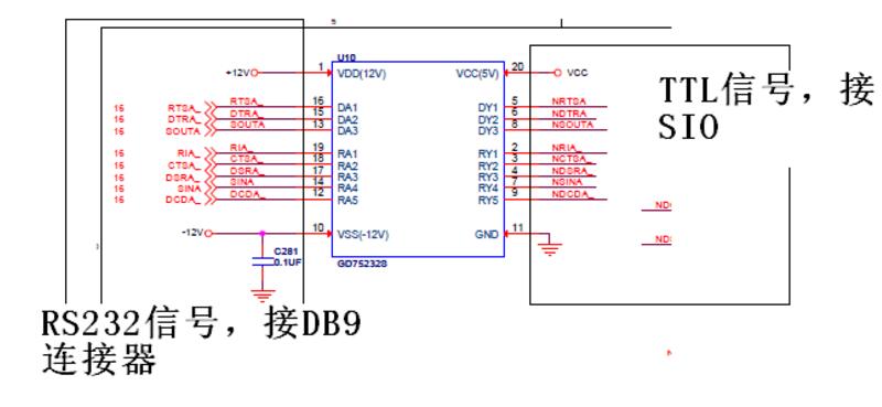
(1) Problem: The motherboard does not boot. From the customer's point of view, when the serial cable is plugged in and unplugged, it smells of burnt. Follow-up will not boot normally.
(2) Measurement analysis:
a. Motherboard U10 (the chip model is TI's GD75232, the function is the serial TTL signal to the serial RS232 signal) is burnt, the peripheral device and the voltage are normal, after replacing U10 the test main board function and the serial port chip (SIO) are normal. The SIO withstand voltage connected to the U10 serial TTL signal is a maximum of 5.5V. Since there is no abnormality in the SIO, it is determined that the U10 burned part is the RS232 part of the external DB9 interface. Check the U10 specification RS232 voltage range: -30 ~ 30V.
b. Measure the NF serial port and the customer, there is a resistance of about 230 ohms between the ground of the USB port of the host computer. Analysis of the bad connection between the USB to serial cable used by the customer. In this way, the upper computer and the ground are not at the same potential and there is a certain voltage difference.
c. The cause of U10 burnout caused by the above judgment is poor grounding. The high voltage introduced through the serial line breaks through U10.
(3). Risk: Poor grounding of the interface causes a potential difference between the ground and RS232 signals of the host computer and the NF, which may cause serial port communication failure, or breakdown and burning of the U10, and may also cause high-voltage breakdown of the SIO chip through the TTL signal after the U10 breakdown.
2. Preventive measures(1) The upper computer and NF are well grounded. The NF chassis, main board ground, and power ground have been well connected by the fixing screws and the interface springs. Good grounding can be done in the following ways:
a. Connect the chassis ground cable to the ground of the equipment room.
b. Ground the power strip connected to the power cord.
(2) The wire rods of the upper computer and NF communication are connected with a good wire. If the USB-to-serial cable used by the above customers is used, a wire with impedance of 0 between the USB interface and the ground of the serial port is required.
Auto Parts,Ac Radiator,Car Radiator Leak,Car Radiator Coolant
Huangshan Kaichi Technology Co.,Ltd , https://www.kaichitech.com