With the development of modern communication technology, communication test instruments continue to evolve. Various new types of equipment have higher and higher requirements for the real-time response capability of the system. The real-time response performance of a communication test instrument becomes one of the key factors for the success of the system design. In many communication test instrument projects, the author successfully applied ARM processor, C51 microcontroller and other embedded systems as the main control chip, realizing the real-time control function of the instrument related modules. Therefore, a design scheme for real-time control using C51 microcontroller in a communication test instrument is proposed.
1 hardware design and implementation
1.1 Overall design
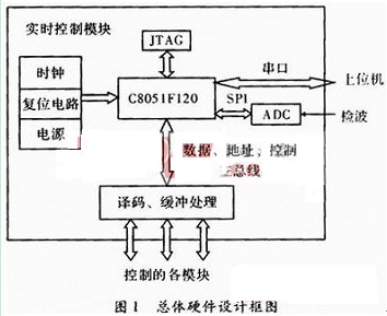
In the communication test instrument, the real-time control module mainly realizes real-time control effects on the radio frequency receiving frequency synthesizing, the radio frequency generating frequency synthesizing, the filter component, the radio frequency input module, and the radio frequency output module. A/D conversion of the RF detection signal to obtain data. Functions such as communication with the host computer.
According to the system function requirements to be realized, considering the system resources and the cost performance of the chip, the embedded system scheme based on C51 single chip is determined. The chip is Silicon Labs C8051F120 with 128 kB on-chip flash memory, 8 ×1 024+256 Byte of on-chip RAM, which can address external data memory interface of 64 kB address space, SPI, UART, timer, clock oscillator, PLL, etc. The on-chip peripheral resources are rich and easy to control.
System resource allocation: RF receiving and transmitting frequency synthesizing module, including DDS, PLL, etc. The external control interface is a micro control interface, so the control is directly implemented by the address, data and control of the single-chip microcomputer. The working state of the filter component, RF input/output module, etc. is related to the level of the signal on the interface, so it is controlled by GPIO. The A/D conversion control uses the serial peripheral interface SPI. The communication with the host computer uses the RS-232 serial port. The overall design block diagram is shown in Figure 1.

1.2 Bus and I / O control design
For the RF receiving frequency synthesizer and the RF transmitting frequency synthesizing module, the bus control is directly used. In order to avoid mutual interference when different modules are controlled, the bus address is decoded by the 3-8 decoder, and the chip selection signals of different modules are generated. At the same time, the data line passes through the bus transceiver to improve the load capacity. For the module with I/O control such as filter component, RF input/output, etc., the GPIO pin of 51 chip is not directly used, then the data bus is latched and the analog GPIO signal is used by the relevant module, as shown in Figure 2. , IO_ / WR1 is generated by B_ / CS7 and the microcontroller write line logic or later.

1.3 SPI and RS232 control interface
The C8051F120 chip itself has an A/D converter, but only 12 bits, which is not suitable for the system. Therefore, an AD7707 from Analog Devices is added to the chip. Its resolution is 16 bits, which is the ∑-â–³ architecture. , converted to the average of the input levels. Three channels, input level range up to ±10 mV~±10 V. According to actual requirements, the system uses AIN3 high level input port, Unbuffered mode, HICOM, REF- is connected to analog ground, VBIAS and REF+ are both connected to +2.5 V The reference voltage, analog power supply 5 V, digital power supply 3.3 V, can detect unipolar levels with an input range of 0 to 10 V. Its control interface is a synchronous serial port, which is directly controlled by the SPI of 51 chips. Figure 3 is an electrical connection diagram of the AD7707. 

Ms001 3000Puffs Vape,Mini Electronic Cigarette,Vape Electric Cigarette,Electronic Cigarette Vape Puff Bar
Guangzhou Yunge Tianhong Electronic Technology Co., Ltd , https://www.e-cigaretteyfactory.com