The Siemens S7-200PLC controller is widely used in the field of industrial control. Its high performance and stability are its biggest advantages. Below we need to connect Siemens' S7-200PLC to EMCP IoT cloud platform to realize remote monitoring and remote monitoring of PC and mobile.
1.1 We need to prepare the following items before dockingOne S7-200 (recommended to use CPU226 or CPU224 PLC with two serial ports, port1 port for program download and online monitoring, port0 for Modbus-RTU slave station and GM10-DTU module for communication). You can also use Smart200PLC (the following is an example of the old 200PLC).
One of the DTU modules of Hebei Blue Bee Technology, antenna and power adapter (hereinafter GM10-DTU is taken as an example).
One SIM card, there is traffic, big card (mobile or Unicom card).
The DP9 needle is a male one.
One networked computer (WinXP/Win7/Win8 operating system)
Electrical tools, wires.
The materials are prepared as follows;
1.2 DTU preparation workRefer to the "GM10-DTU User Manual" for operation here. We need to connect the DTU gateway (the WM10-DTU gateway is similar to the GM10, the following is the GM10-DTU gateway). Connect the antenna and plug in the SIM card (mobile/ Unicom flow card, big card), connect 12V or 24V power adapter.
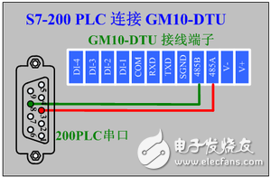
1.3 S7-200PLC preparation work200PLC connected to the power supply (note that the power supply is 24VDC or 220VAC), prepare a 9-pin serial port head (pictured above), and solder the 3 and 8 pins separately with two wires (200PLC system manual is introduced, 3 and 8 pins are 485 communication port). At this point, we connect the 3 pin of the PLC prot0 serial port to the "485A" terminal of the GM10 module, and the 8 pin to the "485B" terminal of the GM10 module.
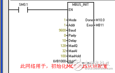
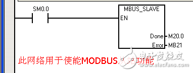
1. Connect the 200PLC to the computer via the programming computer, open the Step7-MicroWin programming software, create a new project, and add the Modbus Slave Port0 function block (MBUS_INIT, MBUS_SLAVE) in the main program.
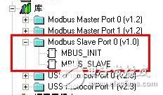
Library file
• The Siemens Modbus slave protocol library consists of two instructions: the MBUS_INIT instruction and the MBUS_SLAVE instruction.
• The MBUS_SLAVE instruction is used to service requests issued by the Modbus master.
• The MBUS_INIT instruction is used to enable, initialize or disable Modbus slave communication. The MBUS_INIT instruction must be executed correctly before using the MBUS_SLAVE instruction. The "Complete" bit is set immediately after the instruction is completed to continue executing the next instruction.
For instructions on the MBUS_INIT and MBUS_SLAVE instructions, please refer to the help in the "STEP 7-MicroWIN" software.
Above we start the Modbus holding register area starting from VB1000 (HoldStart = VB1000), and keep the register as 100 words (MaxHold=100), because the holding register is in words (two bytes), actually this communication buffer is occupied. VB1000 ~ VB1200 a total of 200 bytes.
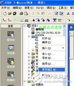
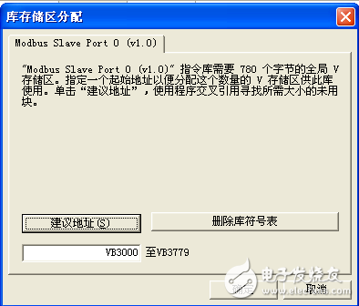
2. Set the stock storage area. Click "File" in the menu bar and select "Stock Storage Area Assignment" in the drop-down box. Enter the starting address of the library in the dialog box that opens. Be careful to avoid the address and other addresses in the program that have been adopted or are ready to be used. You can click "Recommended Address" to avoid overlapping the address occupied by the modbus function block and the register address in the program.
3, compile the program, after compiling correctly, download the program to the PLC through the PPI cable (if the PLC has only one serial port, and this serial port is configured as a modbus port, then we need to move the PLC running switch to the "stop" position in the next program. ), power off after the download is completed, open the program monitor to check whether the output of the "Error" pin of the MBUS_INIT instruction and the MBUS_SLAVE instruction is normal (0 bit is normal, other values ​​are faults, please refer to the fault list in the Siemens PLC technical manual).
Log in to the EMCP platform with an administrator account to set up the EMCP cloud platform. Refer to the EMCP IoT Cloud Platform User Manual for specific operations. After logging in to EMCP, first enter the device list display page, because we have not created any devices, so it is an empty page. Click the "Background Management" button in the upper right corner (only the administrative account has this permission), enter the background of the EMCP platform.

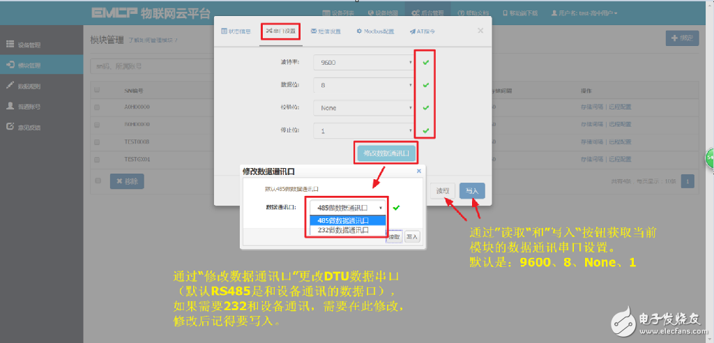
Open the "Background Management - "Module Management" page, bind the DTU to this administrator account, and then use the "Remote Configuration" function to configure the communication parameters and function parameters of the DTU. The most important two places need to be configured, one is the serial port parameter that communicates with the PLC, and the other is the MODBUS channel parameter that sets the DTU timing to collect the PLC data. The following steps are explained in this step. Note: The module can be remotely configured only after it is online. You can also use the “DTU Configuration Software†to configure the module. Refer to the document “DTU Configuration Software User Manualâ€.
3.1.1 Module Binding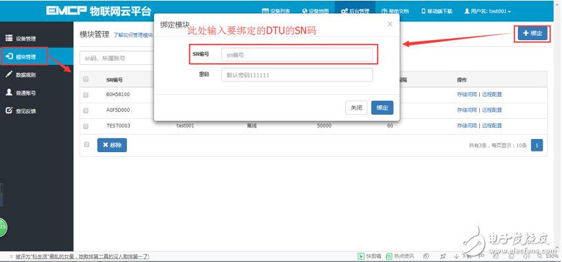
The module initial binding password is 111111, just click on the binding.
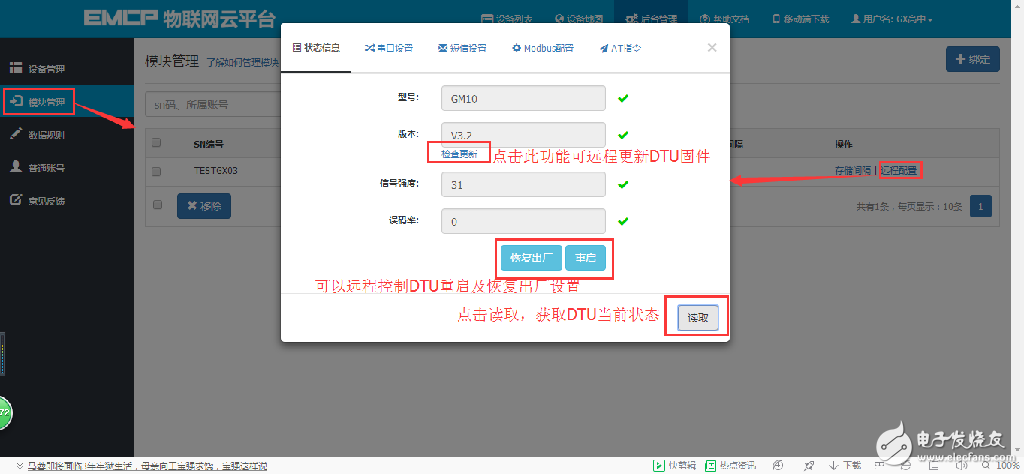
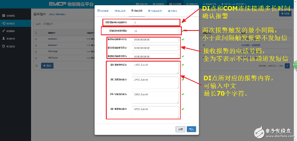
3.1.2 Module Remote ConfigurationThe remote configuration of the module is best to "read" and then "write". Only after the write is successful, the parameter is successfully configured into the DTU. After the "write", it can also be "read" to check whether the previous operation is successful. . If you do not use the module DI alarm point, you do not need to set up SMS.
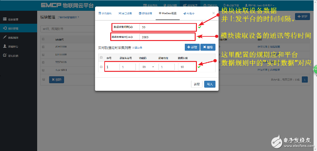
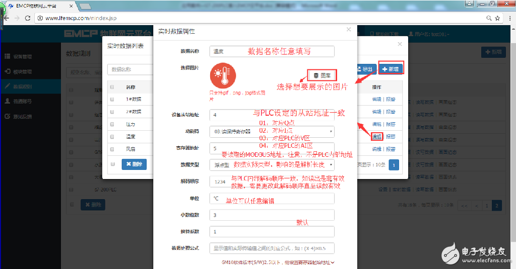
Device slave station number: The MODBUS slave address (range 1-250) of the device connected to the module. This address must be the same as the device slave address. It must be the same as the MODBUS slave number set by the PLC.
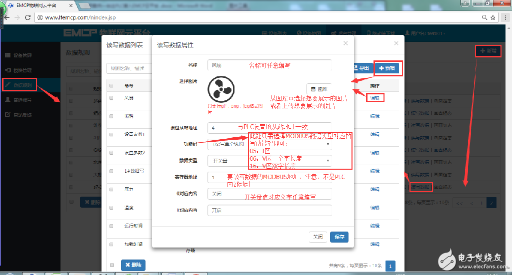
Function code: The identifier of the MODBUS register area of ​​the module reading device. “Function code 01†corresponds to “coil†(0XXXX), “function code 02†corresponds to “discrete input†(1XXXX), “function code 03†corresponds to “hold register†(4XXXX), and “function code 04†corresponds to “input†Register" (3XXXX). In Siemens PLC, Q point corresponds to 01 function code, I point corresponds to 02 function code, V area corresponds to 03 function code, and AI area corresponds to 04 function code.
Start Address: The starting address (excluding the registered area identifier) ​​read by the MODBUS register of the device connected to the module. Figure 1 corresponds to 40001
Data length: The continuous length of the device data read by the DTU. The length in the figure is 10, and 10 data from 40001 to 40010 are continuously read.
A standard DTU can be connected to multiple slaves (up to 4). You can click “New†to create a new sub-device slave. The configuration rules are as described above.
Combined with the establishment of the PLC slave station above, the data read here is 40001 to 40010, which is the data in the VW1000 to VW1019 registers inside the Siemens 200PLC.
Note: When there is an abnormality in the DTU, if the network connection cannot be connected, or the PLC cannot communicate normally, you can use the configuration port (default RS232) to connect to the PC, and use the “DTU Configuration Software†to view the status and abnormal alarm. For details, see “ DTU Configuration Software User Manual.
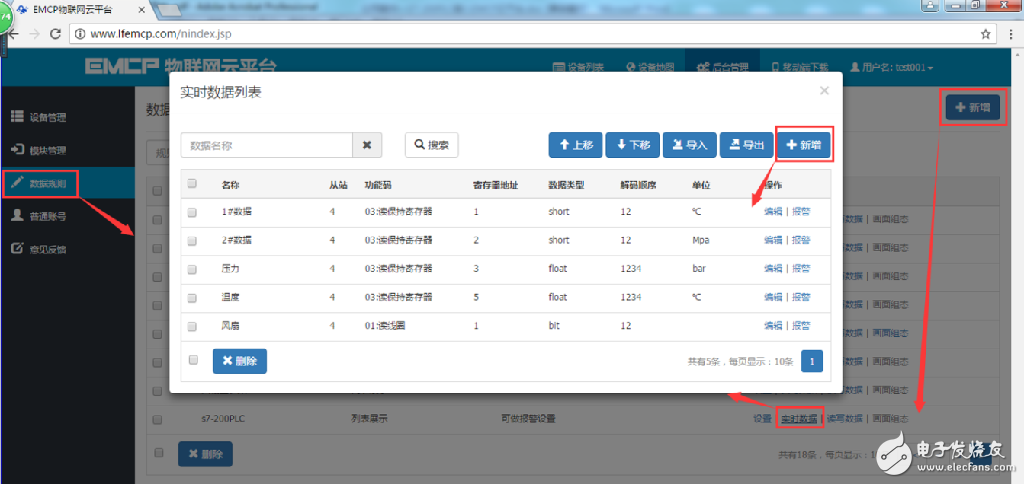
3.2 Creating a new data ruleClick "Data Rules" on the left side of the page to enter the rule setting page, click "Add" in the upper right corner, and set the name of the data rule "S7-200PLC" and the display style "List Display" in the pop-up window. We can choose List display or configuration display, list display: The data we add will be displayed in a fixed list style, and the list display method is simple and convenient (the data test stage can be displayed by a list). Configuration display: We can draw the display style of device data arbitrarily, such as adding graphics, pictures, dashboards, column fills and texts. (This function is similar to the traditional configuration software. Refer to the EMCP Platform Screen Configuration Instructions for Use) document. . After the data rule is created, click “Real Time Data†to add real-time data (Modbus configuration set in 3.1.2), and click “Read and Write Data†to create data for the platform to manually read and write operations. The creation rules are shown below.
Note: Real-time data: It is the DTU according to the configured Modbus acquisition channel (refer to the introduction of 3.1 above), the slave station data is read periodically according to the set collection interval and uploaded to the content displayed on the platform;
Read and write data: no need to configure the Modbus timing acquisition channel in the DTU, and directly perform data read and write operations on the lower device through the platform;
All "register address" settings of the EMCP platform do not need to have a register area identifier. For example, read and write the data of 40019 in the "hold register" (03 function code), and fill in the "register address" in the platform data rule. : If the device Modbus address count starts from 0, you need to add 1 to complete, that is, fill in 20).
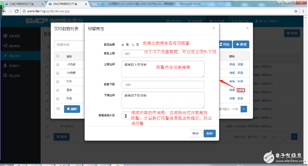
Alarm settings, in the created real-time data, click the "alarm" option to enter the alarm settings page. We can set the alarm upper and lower limits and alarm content of the data and whether to enable this alarm. After the alarm is set, the platform will automatically record the alarm time and alarm value when the data exceeds the upper and lower limits of the alarm. At the same time, the platform will push the alarm message to the APP or WeChat registered by the user.
Create a new device "Device" - "New" to create a new device "Siemens S7-200PLC". The new device is to fill in the basic information of the device. 1 Select the matching image of the device (from the local upload, or not, the system will display the default image);
2 input module SN, input the SN code to be bound, if the SN is not bound before, the binding window will be popped up for binding;
3Select the data rule created above;
4 Click the "Map" button to select the geographic location where the device is located. Click "Save" when done.
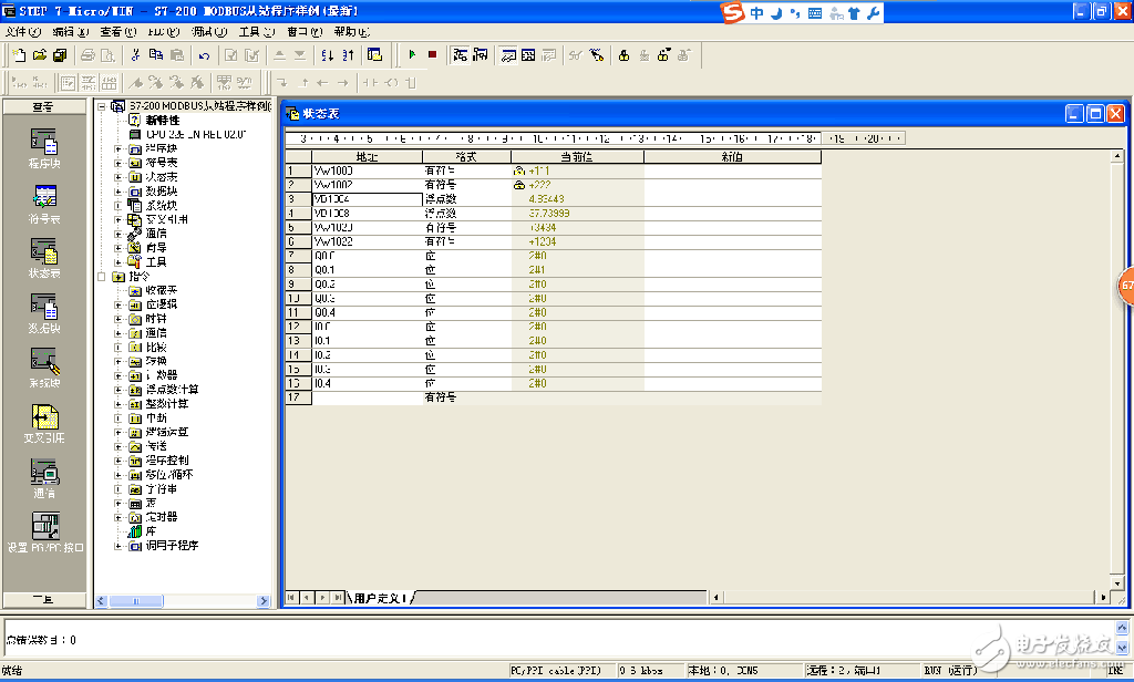
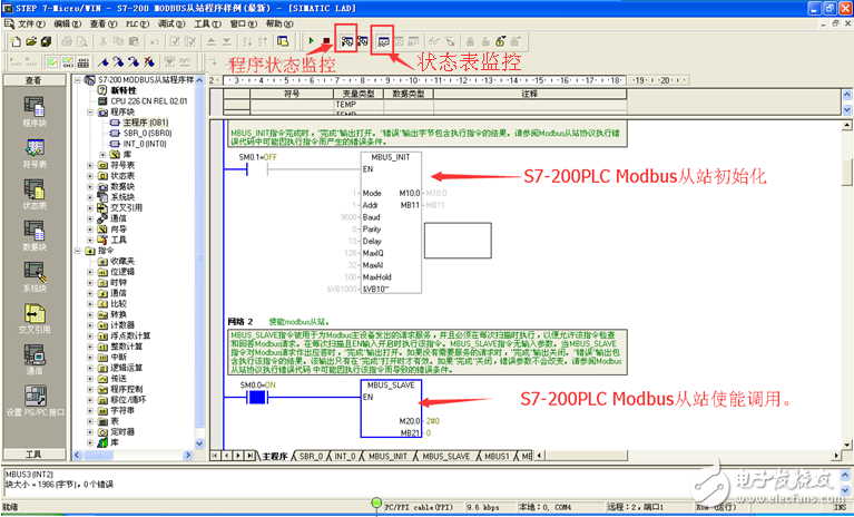
Open the "Program Status Monitor" and "Status Table Monitor" of the Step7-MicroWin programming software to view the running status of the program and the numerical display of the internal data. Through the status table we can view the current value of each data and force the data. As shown below.
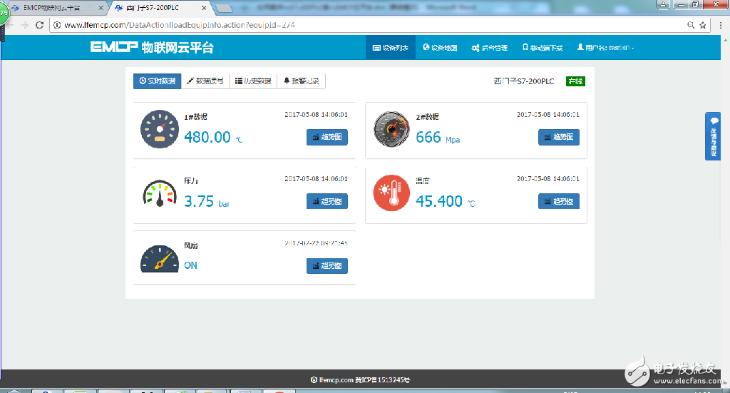
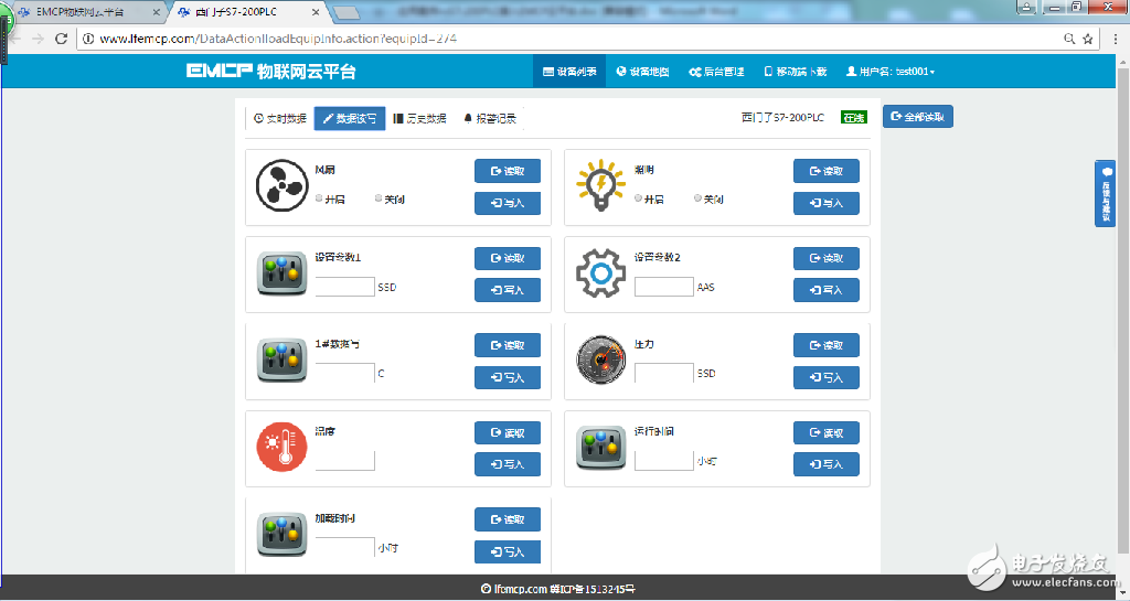
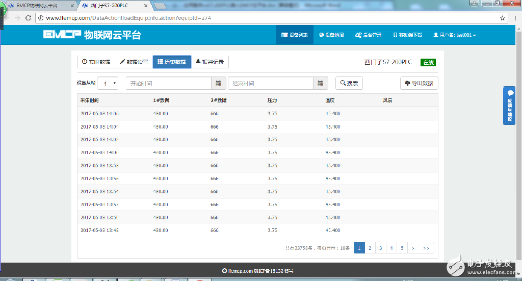
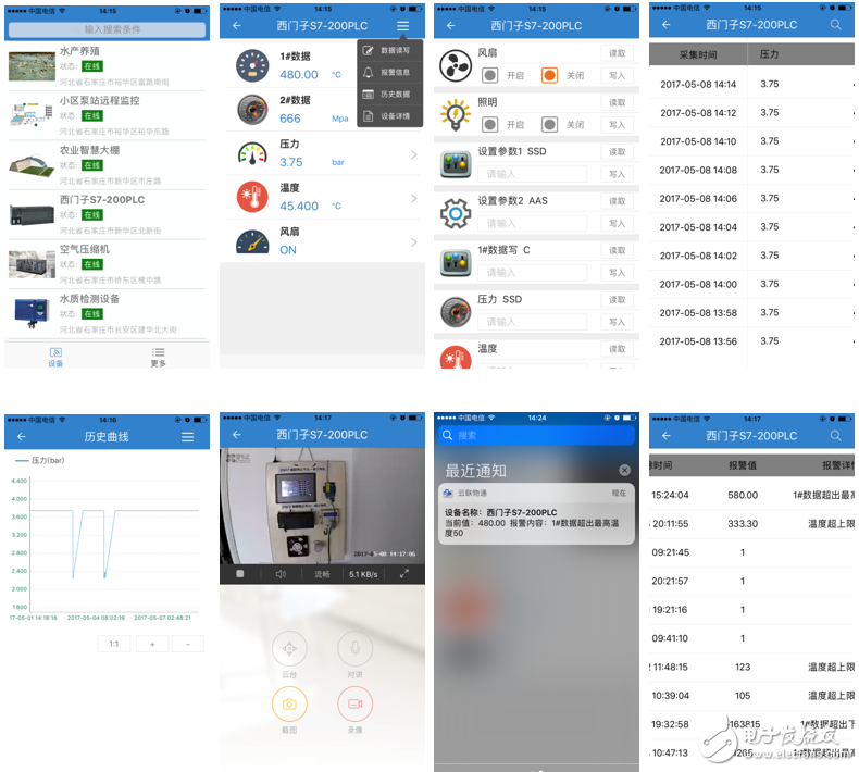
The user logs in to the EMCP platform and clicks on the picture or device name of the "Siemens S7-200PLC" device to enter the device. The first thing to see is the display of 200PLC timing acquisition data (real-time data), click “Read and Write Data†to read and write the 200PLC, click “Historical Data†to view the historical data report of the device timed storage data, click “Alarm Record†to enter The alarm information record report page is displayed as follows.
Install the "Cloud Link" mobile app on your mobile phone (you can scan it by QR code in the upper right corner of the login page of the computer web platform, or download it from major app stores), log in with your username and password, enter the device list and click "Siemens S7" -200PLC" device, directly enter the real-time data list page or configuration screen (under the configuration display mode), click the "triple bar button" in the upper right corner of the menu bar, pop-up function menu, click "read and write data" in the menu Read and write data for reading and writing operations, click “Historical Report†to view the historical storage data report of the device, click “Historical Curve†to view the historical trend graph of each data, click “Alarm Information†to view the alarm record of the device, click “Device†"Details" to view device details or video screens.
a preparation work

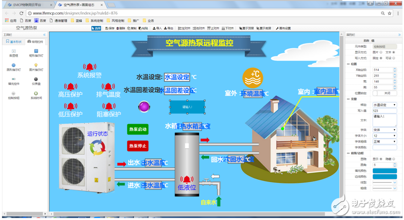
Through the "Background Settings - Data Rules -> Settings - "Configuration Show" steps to choose to use the configuration display form to display the corresponding data rules. After selecting the configuration display, the screen configuration options of the rule become available. Click the "Screen Configuration" option to enter the editing page. Through the configuration editing page, we can freely draw pictures, text, digital display boxes, buttons, indicators, pipes, equipment, etc. For detailed functions, please refer to "EMCP Platform Screen Configuration Instructions".
WeChat pays attention to the "EMCP IoT Cloud Platform" public number, and binds the platform account according to the prompts to use the WeChat monitoring device to receive alarm information. In order to facilitate the management of the equipment, the "EMCP Internet of Things Cloud Platform" public number is "topped".
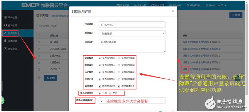
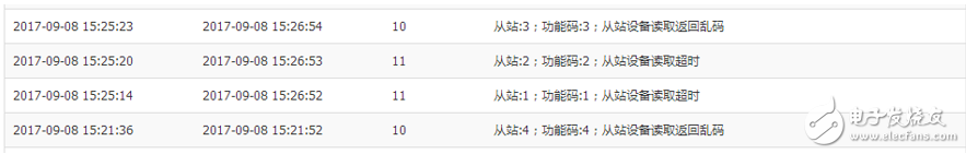
5.3 Turning on communication alarms and authorizing common user functions in data rulesThe communication alarm function is that when the communication between the DTU and the configuration king is abnormal, an alarm will be issued in the corresponding device, and the alarm content is annotated according to the communication abnormality, which is convenient for debugging. The settings and effects are as follows:
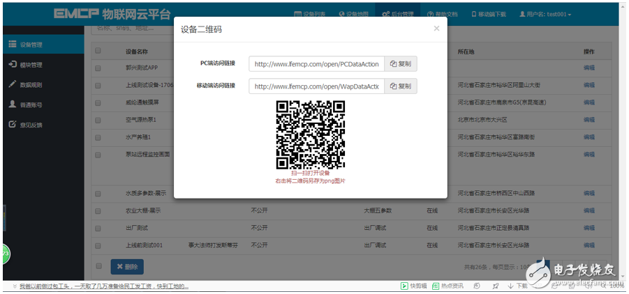
In device management, you can set the device's properties to be public. After the public, it will generate the url connection and QR code of the device. Through the connection and the QR code, you can open the device without logging in. You can also share the device to the social device. ring.
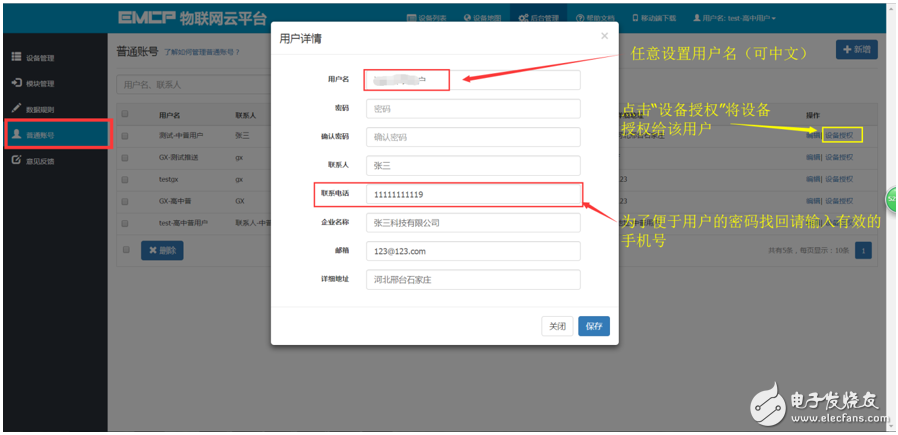
After the administrator account has created the device, you can create a separate account for the user to access the device through the "Ordinary Account" option.
The EMCP platform can realize the access of the fluorite cloud camera, thereby realizing the on-site video monitoring function of terminals such as web, APP and WeChat.
5.7 style customization / system customization service.For large and medium-sized enterprises, we also provide users with platform and software customization services, as described below;
Style customization service: Style customization is to display the user's personalized style based on the original EMCP platform. The entire service is still running on the original EMCP platform server, and the basic contents such as layout, function and architecture are not changed. The style customization content is mainly reflected in the computer webpage, mobile webpage, Android APP, the login domain name of the WeChat public platform, the login page, the platform name, the platform icon, and the like. Suitable for corporate brand building.
Private cloud deployment service: In order to deploy the EMCP system to the user's server, in addition to the display style customization, it is also possible to change the system's function addition, layout display change, and data analysis services.
Contact the Blue Bee sales staff if you need it.
Six, failure analysis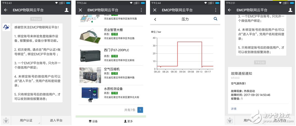
1. The SN code and password are incorrectly bound. The SN code of the device built by the EMCP platform must be the same as the SN code of the connected GM10 module (the SN is located on the right side of the GM10). The password must be the same as the password set by the DTU configuration software (default 111111). .
2. SIM card selection is wrong, you must choose mobile or Unicom SIM (partial China Unicom card is not compatible, it is recommended to use mobile card).
3. SIM card arrears.
4. If the signal strength is lower than 15 or the bit error rate is higher than 3, the DTU may be dropped or unable to be connected to the network. It is better to ensure that the signal strength is above 20 and the bit error rate is 0 (by changing the placement position of the antenna) Adjust the signal strength, which can be obtained by DTU configuration software or remote configuration of the platform module.)
6.2 Reasons why the platform cannot read the Kingview data1. The Modbus slave of the PLC was not created successfully. At this point, we can perform communication test on the PLC through the Modscan32 master station software. If the PLC data cannot be read, then the Modbus slave of the PLC is not successfully created.
2. Wiring error. Connect pin 3 of PLC port0 serial port to 485A of GM10 terminal, and pin 8 to 485B of GM10 terminal.
3. Data creation failed, check if the device created in the data rule is correct.
4. If “Data not acquired†is displayed, please check whether the “Remote Configuration†of the module has the Modbus acquisition channel set. Refer to the settings in 3.1.2. â€
GALOCE Rotary Dynamic Torque Sensors are designed to measure torque of a rotating shaft. Thus, it is necessary to transfer power to the strain gauge bridge, as well as a means to receive the signal from the rotating torque meter or shaft. This can be accomplished using slip rings, wireless telemetry, or rotary transformers. Optionally, sensors can also embed encoder for angle or speed measurement. Torque Sensor, torque transducer or torque meter is a device for measuring and recording the torque on a rotating system, such as an engine, crankshaft, gearbox, transmission, rotor, a bicycle crank or cap torque tester. fastener testing, torque to turn, installation monitoring and torque vs. clamping force.
non-contact Torque Sensor,rotary torque sensor,Torque Power Tester for Motor Speed Measurement,Power Torsion Speed Torque Rotating Sensor Measuring Instrument
GALOCE (XI'AN) M&C TECHNOLOGY CO., LTD. , https://www.galoce-meas.com