The "TD-SCDMA scale network technology application test" implemented by the three major operators of China Mobile, China Telecom and China Netcom by the Ministry of Information Industry is being carried out in Xiamen, Baoding and Qingdao. It is believed that after the trial of the application of this scale network technology, the government will issue a clear policy on the issuance of 3G licenses. According to analysis, the two fixed-line operators China Telecom and China Netcom (or one of them) will likely obtain a license for TD-SCDMA, such an independent TD-SCDMA network will be deployed nationwide. China Telecom and China Netcom are currently operating a PHS network with more than 90 million PHS users, covering almost all the densely populated areas of townships and towns across the country. In this way, it may coexist with the TD-SCDMA system for a relatively long period of time. In particular, the PHS system currently occupies the 20Mhz band of 1900-1920Mhz of TD-SCDMA, so that it is necessary to study the interference coexistence between them. And urgent.
For TD-SCDMA and PHS systems operating in the same area, the interference between them can be divided into four forms: TD-SCDMA base station interference PHS central station, TD-SCDMA terminal interference PHS central station, TD-SCDMA base station interference PHS The subscriber station, the TD-SCDMA terminal interferes with the PHS subscriber station. According to the simulation analysis in [1], the existing RF indicators of the two systems can meet the requirements of coexistence of base station to terminal, terminal to base station and terminal to terminal, and the interference between the two system base stations needs further research. analysis. This report uses deterministic analysis methods to study the interference coexistence of TD-SCDMA base stations and PHS base stations.
2. Deterministic analysis methodSystem A interferes with System B and can be studied using the following interference assessment equation [2]:
Pe(Fi)-MCL(Fi)≤ Imax(Fi) (1)
Where Fi is the frequency of the study;
Pe(Fi) is the transmit power or stray radiation of the interfering transmitter at frequency Fi;
MCL(Fi) is the minimum coupling loss between the transmitter and receiver at frequency Fi;
Imax(Fi) is the maximum interference level acceptable at frequency Fi;
According to the above evaluation equation, according to the interference in different frequency ranges, it can be divided into the following cases:
The useful signal transmitted by the system A transmitter (generally, the power is relatively large), the interference caused by the system B receiving frequency band (except for the adjacent channel) is called blocking interference. It mainly studies the ability of the receiver to resist strong interference signals outside the receiving frequency band. The acceptable maximum interference level (Imax) threshold generally takes the out-of-band blocking characteristic of the receiver.
The out-of-band spurious radiation of the system A transmitter is caused by the interference caused by the system B receiving the passband, which is called out-of-band interference. It mainly considers the receiver's receiving sensitivity to withstand the maximum interference signal level, so that it can accept the maximum interference level (Imax) threshold generally takes the receiver's sensitivity tolerance.
Adjacent channel interference is considered in two aspects: the useful signal transmitted by the system A transmitter, and the interference caused by the system B receiving the first adjacent channel is called adjacent channel interference (in a broad sense, it can be called adjacent channel blocking interference). In addition, the adjacent channel leakage power of the system A transmitter falls into the interference caused by the system B receiver passband, which is also called adjacent channel interference. Thus, the interference generated on the first adjacent frequency of the receiver, the acceptable maximum interference level (Imax) threshold, respectively, takes the adjacent channel selectivity and sensitivity tolerance of the receiver.
As mentioned above, if interference is generated in the receiver passband, the system receiving noise level is raised, which will affect the receiver sensitivity. It is generally considered that the sensitivity loss is reasonable between 0.2 dB and 1 dB. The criterion used in this study is that the base station receiver sensitivity loss is 0.8 dB, and the corresponding TD-SCDMA and PHS base stations can accept the maximum external interference level of -115 dBm/1.28 MHz and -123 dBm/300 khz.
3. Main results of interference analysis3.1. Analyze the system parameters used in the calculation
The literature [3, 4] gives the system parameters such as blocking characteristics, spurious emissions, adjacent channel selectivity and adjacent channel leakage power of TD-SCDMA and PHS (as shown in Table 1). Based on these parameters, Equation (1) can be used to calculate the minimum coupling loss MCL required for different interference situations. The minimum coupling loss between base stations includes the transmit antenna gain, the receive antenna gain, and the isolation loss between the antennas, which can be expressed as:
MCL=IL(dB)-Gain_Tx(dB)-Gain_Rx(2)
Wherein, Gain_Tx is a transmit antenna gain;
Gain_Rx is the receiving antenna gain;
IL is the isolation loss between the two antennas.
Table 1 TD-SCDMA and PHS RF parameters used in deterministic analysis
The deterministic analysis method considered is to study the problem of small coexistence interference in extreme (worst) situations. In the following analysis and calculation, the following assumptions are made: for the smart antenna of the 8-antenna array, on the traffic channel (the TS0 slot control channel is omnidirectional transmission), the multi-antenna synthesis power factor is 9 dB when the antenna is transmitted, and the beam of the smart antenna The shaping factor is 7 dB; when the smart antenna is received, only one beamforming factor of 7 dB is considered. In addition, it is assumed that the gain of the antenna is considered to be the same regardless of whether the coexistence interference analysis is in-band or out-of-band.
Assume that the TD-SCDMA antenna gain is 11 dBi and the PHS antenna is 9 dBi. In the analysis and calculation, the TD-SCDMA transmitting end Gain_Tx=11+7+9=27dB; the TD-SCDMA receiving end Gain_Rx=11+7=18dB; the PHS transmitting end Gain_Tx=9dB; and the PHS receiving end Gain_Rx=9dB.
3.2, TD-SCDMA base station interference PHS base station
The TD-SCDMA base station transmits power on 2010-2025Mhz or 1880-1900Mhz, causing blocking interference in the PHS base station receiver. The blocking characteristic of the PHS base station in the transmission band of TD-SCDMA is -15dBm, and the transmission power of the TD-SCDMA base station is 21dBm (the maximum transmission of the base station is 30dBm, and each user occupies two code channels), so that it can be deduced - When SCDMA and PHS coexist, in order to protect the PHS base station, the minimum coupling loss between the required base stations is MCL = 21 dm - (-15 dBm) = 36 dB.
The TD-SCDMA base station operating at 2010-2025Mhz or 1880-1900Mhz will generate out-of-band interference to the PHS base station. With reference to the 3GPP specifications, when the TD-SCDMA coexists with the 1900-1920Mhz and the asynchronous TDD base station, the transmit power out-of-band spurious radiation The requirement is -39dBm/1.28Mhz=-45.3dBm/300khz, and the receiving sensitivity of the PHS base station is -123dBm/300khz. In this way, it can be inferred that when TD-SCDMA and PHS coexist, the minimum coupling loss between the base stations required to protect the PHS base station is MCL=-45.3dBm-(-123dBm)=77.7dB.
If the working frequencies of the two base stations are further close together, so that they operate at the adjacent frequency of 1900, adjacent channel interference will occur. On the adjacent frequency 1900Mhz of the PHS base station receiving frequency band, the adjacent channel selectivity ACS of the PHS base station is -47dBm. The transmission power of the TD-SCDMA base station is 21dBm. It can be inferred that when TD-SCDMA and PHS coexist, the minimum coupling loss between the base stations needed to protect the PHS base station is MCL=21dBm-(-47dBm)=68dB.
Referring also to the 3GPP specifications, TD-SCDMA has an adjacent channel leakage power of -29 dBm/1.28 Mhz=-35.3 dBm/300 kMhz when it is coexisting with an asynchronous TDD base station at 1900. Considering that the receiving sensitivity of the PHS base station is -123dBm/300khz. In this way, it can be inferred that when TD-SCDMA and PHS coexist, the minimum coupling loss between the base stations required to protect the PHS base station is MCL = -35.3 dBm - (-123 dBm) = 87.7 dB.
3.3. PHS base station interferes with TD-SCDMA base station
According to the system parameters in Table 1, the same analysis method is used to calculate the minimum coupling loss required for the interference of the PHS base station to the TD-SCDMA base station. The minimum coupling loss calculated above and the required isolation loss between the two systems calculated according to equation (2) are summarized in Table 2.
Table 2 Calculates the required isolation loss
It can be seen from Table 2 that when TD-SCDMA and PHS coexist, the interference of PHS to TD-SCDMA is larger than that of TD-SCDMA to PHS (especially when it is out-of-band interference), which is due to the out-of-band miscellaneous of PHS base station. The radiation is relatively large.
4. Discussion on solutions in project implementationFrom the above analysis and calculation, when the two systems of TD-SCDMA and PHS coexist, in order to prevent interference between the two system base stations, the required isolation loss is shown in Table 2. The following discussion analyzes the implementation of these isolation loss requirements by some methods in actual engineering implementation.
4.1. Using space isolation
The spatial attenuation of the signal is calculated using a free-space model of signal propagation (line-of-sight propagation conditions).
Lf=20log(R)+38.12(3)
Where Lf is the free space loss (dB);
R is the distance (m) between two base stations;
Table 3 Required space distance
From the above calculations, it is found that if only space isolation is used to achieve the required isolation loss, then in the extreme case the maximum distance required is 19 km, which is unrealistic in the network arrangement.
4.2, increase the protection bandwidth
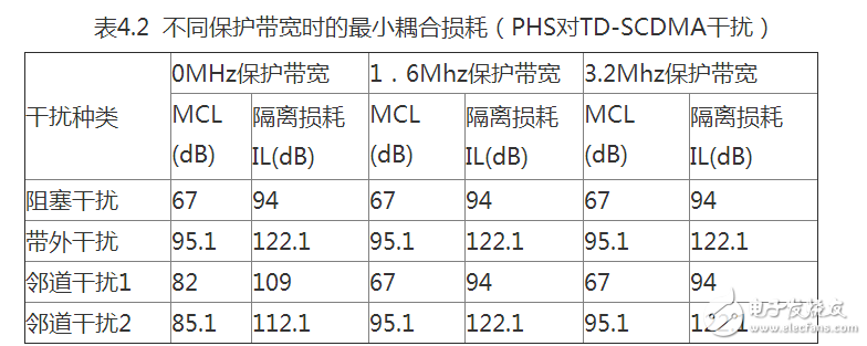
The transmission characteristics of TD-SCDMA have considered the coexistence problem with the non-synchronous TD system when defining the specification. Its adjacent channel leakage power limit is -29dBm/1.28Mhz in the first adjacent channel and the second adjacent channel. . If the two systems have a 1.6MHz protection bandwidth, then its second adjacent channel leakage power falls within the receiver passband of the PHS, which is 87.7dB as the minimum coupling loss required in the case of adjacent channel interference. The minimum coupling loss, when TD-SCDMA transmits a useful signal to the PHS receiver to generate blocking interference (not adjacent channel interference), the minimum coupling loss required is the same as the previous calculation of blocking interference (see Table 4.1).
Similarly, when the protection bandwidth is 3.2Mhz, the adjacent channel interference generated by its adjacent channel leakage power can be considered as out-of-band interference caused by stray radiation, so the minimum coupling loss required is 77.7dB. If you increase the protection bandwidth, they will not improve. Table 4.1 shows the minimum coupling loss for different protection bandwidths.
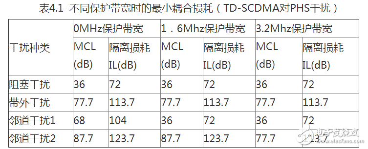
It can be seen from the above that the 1.6Mhz protection bandwidth has little improvement on the TD-SCDMA interference PHS, and the 3.2Mhz protection bandwidth can improve the performance by 10dB (the required isolation loss is reduced by 10dB). There is no significant improvement over 3.2Mhz (out-of-band interference is the main factor).
The adjacent channel leakage power of the PHS system has stricter requirements in the specification, and its out-of-band spurs are relatively large. If the two systems have a 1.6MHz protection bandwidth, then the out-of-band spurs (non-adjacent spurious emissions) are also 794nW/100khz, then the minimum coupling loss is also 95.1dB. At this time, the PHS transmits a useful signal to cause blocking interference to the TD-SCDMA receiver, and the minimum coupling loss required is also 67 dB in the previously calculated blocking interference (see Table 4.2). It can be seen that if the protection bandwidth is increased, they also have no improvement (out-of-band interference is the main factor).
As can be seen from the above, the 1.6Mhz protection bandwidth has basically no change in the improvement of PHS interference TD-SCDMA. From the perspective of a single interference analysis, with this protection bandwidth, it does not play a role in the stricter ACP, but it is very important to have poor out-of-band spurs. This has no meaning to increase the protection bandwidth.
Considering comprehensively, the following conclusions are drawn:
1) 1.6Mhz bandwidth is not improved
2) 3.2Mhz bandwidth can have 10dB isolation loss improvement (TD-SCDMA interference to PHS can increase 10dB isolation loss, otherwise not), but from the combination of the two, 1.6Mhz (including more) of the protection bandwidth can only Improved 123.7-122.1 = 1.6dB.
3) There is no improvement over 3.2Mhz.
Therefore, increasing the protection bandwidth is not an effective method. In addition, the working frequency band of the TD-SCDMA system at this stage is 2010-2025Mhz, and it has a large frequency interval with the PHS 1900-1920Mhz. Therefore, at this stage, there is no need to consider increasing the protection bandwidth.
4.3, increase the filter
It can be seen from the above analysis that it is unrealistic to achieve the required isolation coupling completely through the spatial coupling of the antenna isolation, and the method of protecting the bandwidth is not obvious. Then consider adding a filter directly to the top of the TD-SCDMA and PHS transceivers. According to the previous analysis, the required isolation is calculated. Some main technical indicators of the filter satisfying these isolations are given below.
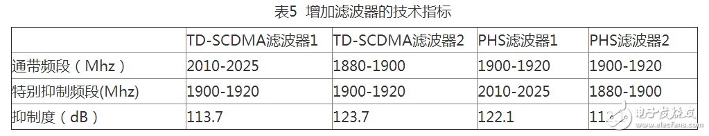
It is important to note that since the out-of-band spur of PHS is relatively large, it is even larger than its adjacent channel leakage power, so that its filter is more stringent than the 1880-1900Mhz in 2010-2025Mhz.
4.4, antenna installation
If the antennas of the two systems are installed close together, such as within 20 meters, they can be considered as a co-site installation. In the case of this co-station, the antenna installation isolation can be calculated using the following empirical formula:
Ih=22+20log(Dh/Lmd)-(Gt(q)+Gr(q))(4)
Iv=28+40log(Dv/Lmd)(5)
Where Ih is the horizontal isolation;
Iv is vertical isolation (non-line of sight);
Dh is the horizontal isolation distance;
Dv is the vertical isolation distance;
Gt(q) is the antenna gain of the transmitting antenna in the q direction with respect to the receiving antenna;
Gt(q) is the antenna gain of the receiving antenna relative to the transmitting antenna in the q direction;
Lmd is the wavelength;
According to the above formula, the total isolation loss of the antenna installation as shown in the figure below can be calculated.
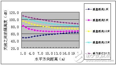
Figure 1 Isolation loss for different antenna installations
It can be seen from the above calculation that the vertical isolation of the two antennas is greater than the horizontal isolation, so it is a good method to install the two antennas vertically. For example, when the difference is 1 meter in the horizontal direction and 20 meters in the vertical direction, the isolation of the two antennas is 109.6 dB. When the distance is 20 meters in the vertical direction and 1 meter in the horizontal direction, the isolation between the antennas is 63.8 dB.
4.5, the results of the discussion
From the above analysis, it can be seen that adding filters at the top of TD-SCDMA and PHS transceivers is the most straightforward method. The filter requirements are shown in Table 5. However, considering the strict requirements of this filter index, the implementation is difficult and the cost is large. In particular, it is difficult to install an additional filter on the PHS base station that has been installed, and other methods can be considered comprehensively. For example, try to make the two systems vertical, and try to increase the distance between the two systems, and use the spatial isolation attenuation of the signal to meet the required isolation loss requirements. However, since the PHS is already an already deployed network that is basically fully covered, it is very difficult to find a place to meet these conditions to install a TD-SCDMA base station.
5 ConclusionThrough the above analysis, we can see that there is interference between the two systems of TD-SCDMA and PHS. The main reason for the interference is that the emission index of PHS is not strict enough, especially the out-of-band spurs are large, for TD-SCDMA. The base station generates interference. TD-SCDMA also interferes with PHS, especially when working with PHS adjacent to the frequency, and which PHS base station the smart antenna beam points to, which will cause large interference. In addition, it can be seen in the analysis that the measures to increase the protection bandwidth are not very obvious. Therefore, in the case where a large number of PHS base stations have been deployed, it is difficult to find a place where the TD-SCDMA base station is installed. Therefore, for TD-SCDMA and PHS. Coexistence interference studies require further research.
UCOAX specializes in custom drawing, flattening, stranding and insulating, cutting and stripping of fine wire and cable .0009" (AWG #48) and larger.
UL iQ for appliance wiring materials
Single-Conductor, Themoplastic Insulation
1007 1015 1061 1185 1126 1227 1330 etc.
Multiple-Conductor, Thermoset Insulation
2464 2468 2725 2835 2990 20276 20379 21100 21118
Single-Conductor, Thermoset Insulation
3173 3265 3266 3271 3272 3302 3346 3347 3363 3383 3385 3386 3619
For more details, please feel free to contact us, thank you.
Ul Wiring Material,Ul Wiring Material Components,Electrical Wire Materials,Wiring Material
UCOAX , https://www.jsucoax.com