The DMA (Direct Memory Access) controller is a unique peripheral that transfers data inside the system and can be thought of as a way to connect internal and external memory to each DMA-capable peripheral through a dedicated bus. Controller. It belongs to the peripheral because it is transmitted under the program control of the processor.
DMA controller structureIn general, the DMA controller will include an address bus, a data bus, and control registers. A highly efficient DMA controller will have the ability to access any resource it needs without the intervention of the processor itself, it must be able to generate an interrupt. Finally, it must be able to calculate the address inside the controller.
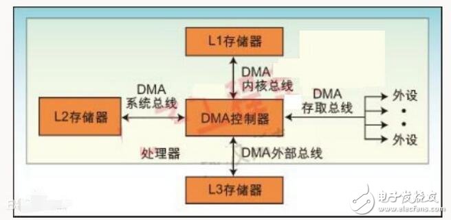
A processor can contain multiple DMA controllers. Each controller has multiple DMA channels and multiple buses that are directly connected to memory banks and peripherals, as shown in Figure 1. Two types of DMA controllers are integrated in many high performance processors. The first type, commonly referred to as the "system DMA controller", enables access to any resource (peripherals and memory). For this type of controller, the number of signal cycles is counted by the system clock (SCLK). Take ADI's Blackfin processor as an example, the frequency can be up to 133MHz. The second type, called the Internal Memory DMA Controller (IMDMA), is dedicated to inter-access operations between locations where internal memory is located. Since access occurs internally (L1-L1, L1-L2, or L2-L2), the count of the number of cycles is based on the core clock (CCLK), which can exceed 600 MHz.
Each DMA controller has a set of FIFOs that act as a buffer between the DMA subsystem and the peripheral or memory. For MemDMA (Memory DMA), both the source and destination of the transmission have a set of FIFOs. When the resources are tight and the data transfer cannot be completed, the FIFO can provide a temporary storage area for the data, thereby improving performance.
Because you usually configure the DMA controller during code initialization, the kernel only needs to respond to the interrupt after the data transfer is complete. You can program the DMA control to move data in parallel with the kernel while allowing the kernel to perform its basic processing tasks—those that should let it focus on completion.
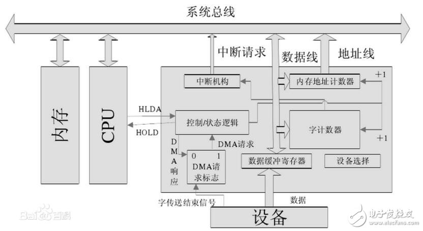
A DMA controller is actually an interface circuit between a DMA-based peripheral device and a system bus. This interface circuit is composed of a DMA mechanism based on the interrupt interface. It is customary to refer to the DMA mode interface circuit as a DMA controller.
(1) Memory address counter: The address used to store the data to be exchanged in the memory. Before the DMA transfer, the data must be sent to the memory address counter by the program in the starting position (first address) in the memory. When the DMA transfers, the address counter is incremented by "1" every time the data is exchanged, thereby giving the address of a batch of data to be exchanged in the memory incrementally.
(2) Word counter: used to record the length of the transmitted data block (how many words). The content is also preset by the program before data transfer, and the number of words exchanged is usually expressed in complement form. At the time of DMA transfer, the word counter is incremented by "1" for each word transmitted. When the counter overflows, the highest bit generates a carry, indicating that the batch of data is transferred, thus causing the DMA controller to send an interrupt signal to the CPU.
(3) Data buffer register: used to temporarily store data (one word) for each transfer. When input, it is sent to the data buffer register by the device (such as a disk), and then sent to the memory by the buffer register through the data bus. Conversely, when outputting, the memory is sent to the data buffer register through the data bus and then sent to the device.
(4) DMA request" flag: A control signal is given every time the device prepares a data word, so that the "DMA request" flag is set to "1". When this flag is set, a DMA request is issued to the "control/status" logic. The latter sends a bus usage right request (HOLD) to the CPU. After responding to the request, the CPU sends back a response signal HLDA. The "control/status" logic receives the signal and sends a DMA response signal to reset the "DMA request" flag. Exchange the next word to be prepared.
(5) Control/Status logic: consists of control and timing circuits and status flags, etc., used to modify the memory address counter and word counter, specify the transfer type (input or output), and the "DMA request" signal and CPU response signal. Coordinate and synchronize.
(6) Interrupt mechanism: When the word counter overflows, it means that a group of data is exchanged, the interrupt mechanism is triggered by the overflow signal, and an interrupt report is reported to the CPU.
Ups Lithium Ion Battery,Uninterruptible Power Battery,Stability Lithium Ion Battery,High Power Stability Battery
Wolong Electric Group Zhejiang Dengta Power Source Co.,Ltd , https://www.wldtbattery.com