Special offer 0603 red light LED quality assurance
Circuit Operation Principle Reading Vision Health Table Lamp Circuit consists of power supply circuit, infrared emission circuit, infrared receiving and amplifying circuit, voltage doubler detection circuit, electronic switch circuit, ambient brightness detection/lighting alarm circuit, audible alarm circuit and function control/dimming circuit. As shown in Figure 9-73.
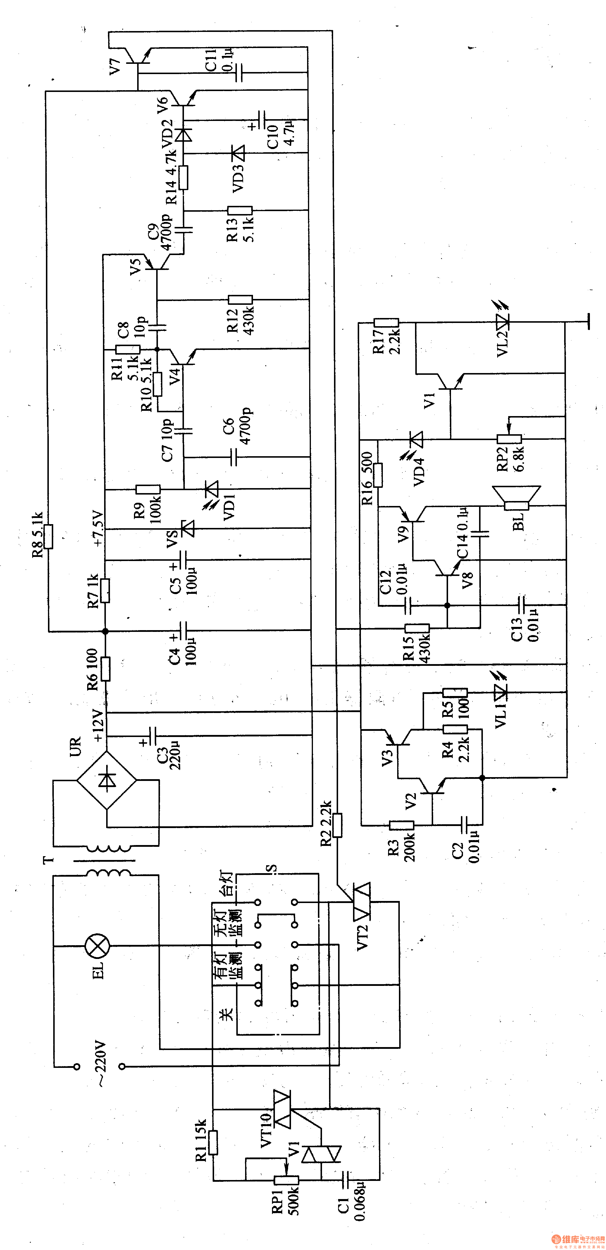
The power circuit is composed of a power transformer T, a rectifier bridge stack UR, filter capacitors C3, C4, C5, current limiting resistors R6, R7 and a Zener diode VS.
The infrared transmitting circuit is composed of a resistor R3-R5, a capacitor C2, transistors V2, V3 and an infrared light emitting diode VLl.
The infrared receiving and amplifying circuit is composed of an infrared photodiode VD1, a resistor Rg-R11, capacitors C6 and C7, and transistors V4 and V5.
The voltage doubler detection circuit is composed of capacitors C9, ClO, resistors R13, R14 and diodes VD2, VD3.
The electronic switching circuit is composed of resistors R2, R8, a capacitor C11, transistors V6, V7, and a thyristor Vm.
The ambient brightness detection/lighting alarm circuit is composed of a photodiode VD4, a potentiometer R-total, a transistor Vg, a resistor R14 and an alarm indicating light-emitting diode V愧.
The audible alarm circuit consists of resistors R5, R6, capacitor C2-call, transistor V8, Vg and speaker BL.
The function control / dimming routing function switch SL resistor Rl, potentiometer RPl, capacitor Cl, bidirectional trigger diode VlO and thyristor VTl.
The function switch S has 4 levels of "off", "lighted monitoring", "no light monitoring" and "table lamp". When S is placed in the "OFF" position, the primary circuit of the power transformer T is disconnected by S, and the entire circuit does not operate.
When S is placed in the "lamp monitoring" position, the AC 220V voltage is depressurized by T, UR rectified, and C3 filtered to generate +l2V voltage, which is supplied to the infrared transmitting circuit, ambient brightness detection/lighting alarm circuit and sound alarm circuit; After R6 and R8 current limiting, the voltage is applied to the base of V7; the other circuit is R6, R7 current limiting, C4, C5 filtering and VS voltage regulation to generate 7.5V voltage, which is supplied to the infrared receiving and amplifying circuit.
The RC frequency selective oscillator composed of V2, V3 and R3, R4 and C2 is energized and oscillated to drive VLl to emit an infrared signal.
After the dimming circuit is energized, VTl is triggered to turn on, and the illumination lamp EH is lit.
Adjusting the resistance of RPl can change the conduction angle of VT1, thereby changing the luminance of EH.
When the user's reading and writing distance is normal, VDl will receive a strong infrared signal and convert it into a corresponding electrical signal. This electrical signal is turned on by W and V5 amplification and voltage doubler detection circuit to make V6 turn on, V7 By the end, the audible alarm circuit does not work.
If the user's reading and writing distance is too close, VDl can not receive the infrared signal or the received infrared signal is weak, then V6 is cut off, V7 is saturated, and Vm is turned off, EL is extinguished; meanwhile, by V8, V9 and The audio oscillator composed of Cl2-C14 oscillates and the BL sounds an alarm.
When the ambient brightness is suitable for reading and writing, the internal resistance of VD4 is small, then Vl is turned on, VL2 does not emit light; when the brightness is low, the internal resistance of VD4 becomes large, so that Vl is cut off, VL2A is bright, indicating that the ambient brightness is not suitable for reading. write.
When S is placed in the "no lamp monitoring" position, the dimming circuit does not work, and the EL does not emit light. At this time, only the read/write distance monitoring, the ambient brightness monitoring circuit, and the alarm circuit work.
When S is placed in the "table lamp" position, only the dimming circuit works, the EL lights up, and the monitoring circuit and the alarm circuit do not work.
Adjusting the resistance of RPl can change the sensitivity of light control.
Component selection
Rl, R6 and R8 use 1/2W metal film resistors; R2-R5, R7 and R9-Rl6 all use 1/4W metal film resistors.
RPl selects 2W or more synthetic carbon film potentiometer; RP2 selects small synthetic carbon film potentiometer or variable resistor.
Cl selects CBB capacitors; C2-C5 and ClO select aluminum electrolytic capacitors with a withstand voltage of 16V; C2 and C11-C14 select monolithic capacitors; C6-C9 selects high-frequency ceramic capacitors or glass glaze capacitors.
VDl selects RPM-301B infrared photodiode; VD2 and VD3 select 1N4148 silicon switch diode; VD4 selects 2DU series phototransistor.
VS selects silicon steady voltage diode of lW and 7.5V.
VLl selects HG301 type infrared light-emitting diode; V愧 selects d3mm red high-brightness light-emitting diode.
Vl, V2, V4, V6-V8 select S9014 type silicon NPN transistor; V3, V5 and V9 select S9015 type silicon PNP transistor; VlO selects DB3 type bidirectional trigger diode.
Both VTl and VT2 use several C336A (3A, 600V) type bidirectional thyristors.
S uses a bipolar four-bit band switch.
UR selects the rectifier bridge stack of lA and 5OV.
BL uses 0.25W, 8Ω electric speakers.
T selects 3W, the secondary voltage is l2V power transformer.
The EL uses a 40-60W incandescent bulb.
ZTTEK Electric Scooter Batteries. Any size batteriesb can be customized! Suitable for most electric vechile modles, like electric e-bike, golf cart,forklift,beach electric motorcycle.
Electric Motorcycle Battery,Li-Ion Battery Pack For Electric Bike,Lithium Battery Charger For Electric Bike,Lithium Battery Pack For E-Bike
Jiangsu Zhitai New Energy Technology Co.,Ltd , https://www.zhitaibattery.com