1 Introduction
High-power white LEDs are a new generation of semiconductor light sources that are non-linear loads. Since the load characteristics cannot be described in a wide range and accurately, the light-emitting characteristics of the LED cannot be effectively controlled by the voltage type driver. When the load voltage has a slight fluctuation, it can cause a large change in the current, so that the brightness changes greatly. If the load voltage fluctuates too much, the LED may burn out. The LED load current is closely related to the LED's brightness, color temperature, efficiency, luminous flux, and lifetime. Therefore, ultra-high brightness LEDs are usually driven by a constant current source. Although the power efficiency of high-power white LEDs is relatively high, the overall efficiency depends not only on the LED itself, but also on the driver circuit. Therefore, designing a current-mode switching converter is an ideal driving scheme for meeting the high power and high efficiency requirements of LED applications.
2 LED driver design ideas
Since the driver is mainly used for automotive lighting, its power supply is mainly a battery, so a DC/DC converter is needed to accurately adjust the constant current of the LED, thereby obtaining the consistency of the light intensity of the LED and the color integrity. The LED lighting working mode of the in-vehicle system varies widely, so the driver should also be suitable for different application needs. The standard voltage for a car battery is 12 V, and the battery voltage may drop to 8 V when the battery is running out, and the alternator may charge its voltage to 14 V while the engine is running. Since the battery cell voltage varies widely, the required output voltage may be higher or lower than the input voltage. Therefore, the LED driver needs to adopt a step-up and step-down circuit structure to accommodate the constant current requirement of the LED.
Considering the essential characteristics of the LED driver as the current control system, the general-purpose switching power supply chip MC33167 is selected as the core device. It uses 7.5~40 V low-voltage DC power supply. The internal switching current of the chip can reach up to 5 A, and the appropriate peripheral circuit is configured. The up-and-down function can be implemented, so the chip can be used as the core chip of the LED driver for automobiles.
3 Analysis and Research of Switching Power Core Chip
The switching power supply chip of LED special lighting driver adopts MC33167, which can provide various functions. Its internal structure is shown in Figure 1. If the output switch current exceeds 5 A, 5 V output can be provided without external resistors. The internal 2% accuracy reference source can provide under voltage protection and internal thermal protection. Various protection modes can make the circuit work safely. . The protection mode reduces the supply current to 36μA, which greatly reduces the power consumption of the chip. The built-in 72 kHz fixed frequency oscillator allows the switching power supply to output a higher frequency PWM, so a smaller inductor and capacitor can be used outside the chip to achieve filtering, which greatly simplifies external components.
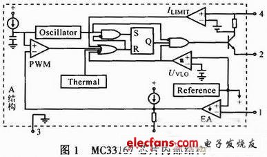
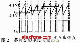
The correspondence between the potential 5 of the chip 5 and the output potential U2 is as shown in FIG. 2 . When the potential of the chip 1 pin U1 changes (when U1 is not equal to the standard voltage of 5.05 V), U5 changes proportionally. U5 and the sawtooth wave generated by the crystal oscillator are compared with the PWM operational amplifier to output high level or low level. U2 is controlled by internal logic circuit operation to control the on or off of the switch. Therefore, with the change of U5, the switching time of the output switching tube is different, that is, the ratio of U2 changes, thereby controlling the magnitude of the output voltage. When U1 decreases, U5 rises, while the duty ratio of control U2 rises, and the average value increases, so input U1 changes inversely with output U2. Therefore, a negative feedback circuit can be added outside the chip to form a stable power supply.
Dongguan Yijia Optoelectronics Co., Ltd. , https://www.everbestlcdlcms.com