1 Introduction Inverter often encounters unexpected voltage transients and surges during use, which leads to damage to the internal electronics of the inverter. The damage is caused by the semiconductor devices in the inverter (including diodes, transistors, thyristors and integrated circuits). Circuits, etc.) are burned or broken down. According to statistics, 75% of faults in the inverter control section are caused by transients and surges. Voltage transients and surges are everywhere. Power grids, lightning strikes, blasting, and even people walking on carpets can generate tens of thousands of volts of static-induced voltage, which are invisible sources of damage to the control ports and communication ports of the inverter. Therefore, in order to improve the reliability of the inverter, it is necessary to take protective measures against voltage transients and surges.
2 lightning protection port According to the engineering practice of the frequency converter application, the frequency converter can be roughly divided into direct lightning strike, induction lightning and conductive lightning by lightning strike. However, the arrival of the device in any form can be summarized as lightning surges intruding from the following four locations. These parts are referred to herein as lightning protection ports, and are illustrated by a frequency converter.
2.1 Shell Ports For example, we can treat any large or small frequency converter or system as a whole, such as sensors, transmission lines, signal relays, field instruments, dcs systems, etc., all of which may be completely exposed. Direct lightning strikes in the environment, resulting in equipment damage. The standard stipulates that when the equipment casing is subjected to lightning discharge of 4kV, it will affect the normal operation of the inverter or system. For example, a sensor placed in an outdoor input frequency converter may be exposed to lightning contact discharge; a frequency converter cabinet located indoors may be subjected to a space discharge when the lightning protection lead of the building is discharged.
2.2 Signal Line Port In the inverter control system, in order to realize the transmission of signals or information, there must always be a connection with the outside world. These signal interfaces from the external input signal or the inverter output may be affected by lightning surges. Because the external signal input to the inverter port of the inverter cabinet often passes through the long cable, the 10/700μs waveform is adopted. The standard specified line-to-line surge voltage is 0.5kV, and the line-to-ground surge voltage is 1kV. The port that transmits signals between the inverters in the building is subjected to a surge impact equivalent to the surge on the power line. 1.2/50 (8/20) μs combined wave, line-to-line, line-to-ground surge voltage limit is used. constant. Once the limit is exceeded, the signal port and the device behind the port may be damaged.
2.3 Power Port The power port is the most widely distributed and most susceptible to inductive or conductive lightning surge. The power port of the inverter is from the power distribution panel to the inverter power input and from the inverter output to the motor. The standard specifies a surge voltage limit of 0.5kV between line and line for a 1.2/50 (8/20) μs waveform and a line-to-ground surge voltage limit of 1kV. However, the surge voltage here indicates that the working voltage is 220V AC. If the working voltage is low, it cannot be used as the standard. The small surge impact on the power line does not necessarily damage the equipment immediately, but at least affects the life. .
2.4 Grounding Port Although there is no specific reference to the grounding port in the standard, the grounding port of the inverter is actually very important. When the lightning occurs, the grounding port may be affected by the ground potential counterattack and the ground potential increase, or the grounding resistance may be too large due to poor grounding and improper grounding, and the equipment may not be damaged due to the reference potential requirement. The grounding port not only has requirements for the grounding resistance/grounding pole (length, diameter, material, etc.), grounding method, grounding grid, etc., but also has a direct relationship with the electrical characteristics, working frequency band, working environment, etc. of the equipment. At the same time, it is possible to counterattack the DC working power port in the inverter from the grounding terminal, and damage the unit circuit with DC as the working voltage. In summary, the lightning protection of the inverter can be considered from the four key ports, as shown in Figure 1. 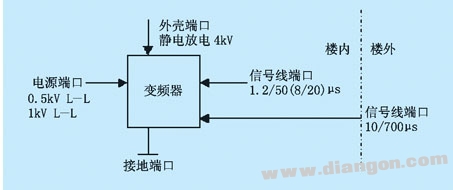
Figure 1 Four key ports of the inverter
3 inverter port protection
3.1 Enclosure Port The enclosure port protection of the inverter is not only the building envelope, but also the enclosure of the inverter or the enclosure of the inverter cabinet, such as the inverter and the inverter cabinet. The scope of application of the first part (General Principles) of IEC 1312-1 "Protection of Lightning Electromagnetic Pulses" is: design, installation, inspection and maintenance of an effective lightning protection system for a frequency converter system in a building or at the top of a building. There are three main protection methods: grounding, shielding and equipotential bonding.
(1) Grounding
IEC1024-1 has described the lightning protection grounding method of buildings, mainly through the underground mesh grounding system of buildings. When the inverter system is lightning-proof, it also requires the power line passing between two adjacent buildings. The signal transmission cable must be connected with the building grounding system (cannot form a loop) to reduce the current in the cable by using multiple parallel paths. .
The grounding of the inverter system should pay more attention to the safety of the system and prevent other system interference. Generally speaking, the grounding of the inverter system under working conditions cannot be directly connected to the lightning protection ground wire, otherwise there will be stray current entering the inverter system causing signal interference. The correct connection method should connect two different grounding nets underground through the arrester low-voltage arrester to automatically connect them in the lightning strike state.
(2) Shielding Theoretically, shielding is very effective against lightning protection of the inverter casing. However, from an economical point of view, different shielding methods should be selected from the requirements of equipment component immunity and shielding effectiveness. Line shielding, that is, the use of shielded cables in inverter systems has been widely used. However, shielding of equipment or systems is subject to availability. The IEC proposes an example of measures to connect building reinforcement to a metal frame.
IEC 1312-2 is described as follows: The main source of electromagnetic interference in a building's internal frequency converter system is the transient magnetic field caused by the instantaneous current of several lightning strikes during a single flash. If the building or room containing the drive system is shielded with a large space, the instantaneous electric field is usually reduced to a sufficiently low value under such measures.
(3) The purpose of equipotential bonding equipotential bonding is to reduce the potential difference between the inverters and between the inverter and the metal parts. The equipotential bonding at the interface of the lightning protection zone should take into account the inverter system in the building. Where those requirements for lightning electromagnetic pulse are minimal, the equipotential bonding zone is preferably metal plate and multiple times with the building. Reinforcing bars are attached or attached to the components of other shields. For the exposed conductive material of the inverter system, an equipotential connection network should be established. In principle, a potential connection network does not need to be directly connected to the earth, but in fact all equipotential connection networks have a large ground connection.
3.2 Signal Line Port Signal Line Port Protection There are many types of more mature protection devices, such as inverter signal port protector and inverter communication port protector. In addition to the performance of the protector itself, attention should be paid to the protection device's transmission rate, insertion attenuation limit, standing wave ratio, operating voltage, operating current and other related indicators. If multi-level protection is used in the same system, it should be Consider the issue of mutual cooperation.
Transient currents in the signal port are most likely to damage the internal signal exchange or conversion unit and control unit of the inverter, such as the main board, parallel port, signal interface card, etc. In fact, transient currents or surges may be introduced into the signal transmission network through different channels. If the inverter control system and the host computer communicate with an Ethernet structure, four possible network pairs are listed in the IEEE802-3 Ethernet standard. The situation that caused the threat:
(1) direct contact between the local area network component and the power supply circuit or the circuit affected by the power;
(2) Static effects on LAN cables and components;
(3) High-energy transient current is coupled to the local area network system (introduced by a cable near the network cable);
(4) There are small differences in the ground voltages of the network components connected to each other (for example, the safety ground voltages of two different buildings may be slightly different).
Taking the inverter communication line as an example, in the RS-232 string and parallel port standard, the ground line for discharging high-energy surges and fault currents shares a line with the return path of the data signal, and as small as several tens of volts. The transient voltages are likely to destroy the host computer and terminals through these serial and parallel ports. The signal transmission line can also directly transmit transient surges on the outdoor power line, and the signal interface can conduct lightning and static leakage. The surge voltage caused.
Users should carefully choose the data line protector. Although some protectors play a "split" role, they often connect a silicon avalanche diode (SAD) between the protected line and the protector housing. The test shows the clamping performance of the SAD. Very good, but it has limited surge shunting capabilities. At the same time, the varistor (MOV) cannot be used on the data line protector. The signal interface lightning protection device of advanced process control system (whether RS-232 string communication interface or computer coaxial network adapter interface) currently uses transient over-voltage semiconductor discharge tube, and its impact residual voltage parameter is very important. It is better to adopt a multi-level protection design circuit when conditions permit.
3.3 Power port In principle, multi-stage SPD is used for power protection. However, the power supply protection of the inverter control system must use a lower residual voltage protection device due to its sensitivity, and this residual voltage should be lower than the withstand voltage required to protect the device. ability. At the same time, the influence of electromagnetic interference on the inverter system must also be considered, so the filtered shunt design should be more ideal. Therefore, two points that pay special attention to the power supply protection of the inverter system are: the first two stages use a protector with a large flow capacity, and at the end of the inverter, a protector with a low residual voltage is used. It is preferable to have a filter circuit in the last stage of the protector. Pay attention to the following issues when installing SPD on the power supply port of the inverter system:
(1) Multi-stage SPD should consider energy coordination, time coordination, and distance coordination. If you don't cooperate properly, the effect will be counterproductive.
(2) The leads connecting the lightning protection devices should be as thick and short as possible.
(3) Whenever possible, bundle all the connecting wires together.
4 Conclusion In the variable frequency speed control transmission system, paying attention to the port protection of the inverter has become a problem that must be faced in the design and application of the frequency conversion variable frequency speed control transmission system, and also one of the key problems in the application and promotion of the frequency converter. The port protection problem of the inverter will be continuously developed and improved.
Mini 500Puffs,Mini 500Puffs Disposable,Mini 500Puffs Disposable Vape,Mini 500Puffs Grape
Lensen Electronics Co., Ltd , https://www.lensenvape.com