Surge current refers to the peak current flowing into the power supply device at the moment the power is turned on. Since the input filter capacitor is quickly charged, this peak current is much larger than the steady state input current. The power supply should limit the level of surge that AC switches, rectifier bridges, fuses, and EMI filter components can withstand. Repeatedly switching the loop, the AC input voltage should not damage the power supply or cause the fuse to blow. Inrush current also refers to the non-repetitive maximum forward overload current that causes the junction temperature to exceed the rated junction temperature due to abnormal circuit conditions.
Inrush current suppression circuit----switching power supply surge suppression circuitWhen the switching power supply is powered up, it will generate a high surge current. Therefore, a soft start device to prevent inrush current must be installed at the input end of the power supply to effectively reduce the inrush current to the allowable range. The inrush current is mainly caused by the charging of the filter capacitor. At the instant when the switch tube starts to conduct, the capacitor exhibits a lower impedance to the AC. If no protection measures are taken, the inrush current can approach hundreds of A.
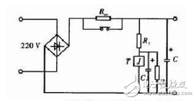
The input of the switching power supply generally adopts the capacitor rectification and filtering circuit as shown in Fig. 2. The filter capacitor C can be used with low frequency or high frequency capacitors. If low frequency capacitors are used, parallel high frequency capacitors of the same capacity should be connected to bear the charging and discharging current. The current limiting resistor Rsc that is connected between rectification and filtering in the figure is to prevent the impact of the inrush current. When the switch is closed, Rsc limits the charging current of capacitor C. After a period of time, the voltage on C reaches the preset value or the voltage on capacitor C1 reaches the operating voltage of relay T, Rsc is short-circuited and completed. At the same time, circuits such as thyristors can be used to short the Rsc. When the switch is closed, the capacitor C is charged through the Rsc because the thyristor is turned off. After a period of time, the thyristor is turned on, thereby short-circuiting the current limiting resistor Rsc.
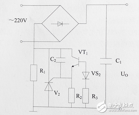
Inrush current suppression circuit----anti-boot surge current circuitAt the moment of starting, the surge current is very large, the voltage drop of R1 is very large, VS2 reverse breakdown → VT2 saturation → V2 trigger pole is shorted → V2 cutoff → the starting current is all from the current limiting resistor R1 through → R1 to limit The role of inrush current. The large filter capacitor C1 is charged, the load enters the normal working state → the current of R1 becomes the normal current → the voltage drop across R1 decreases → VS1 cuts off → VT1 cuts off → V2 gets the trigger voltage from the R1 branch → V2 turns on → R1 is next to Road → R1 does not consume power.
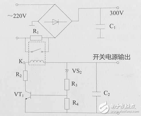
Just starting up, the power supply has not been working normally, there is no voltage at both ends of C2 → VS2 cutoff → VT1 cutoff → K1 coil no current → K1 normally open point (switch) disconnected → surge current flows through R1, current limiting surge current. After the power supply works normally → VS2 is turned on → VT1 is turned on → K1 normally open point (switch) is closed → R1 is shorted → R no longer consumes power.
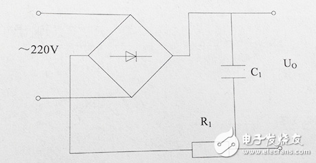
At the moment when the device is just turned on, the initial voltage on the capacitor C1 is zero, so the initial charging current of C1 is very large. After the power is turned on, the circuit is normal and the current returns to the normal value. This moment, the large current becomes a surge circuit. In addition, lightning dry grid can also cause surge voltage and surge current. R1 in the figure below is a high-power resistor with only a few ohms and about 10W. It is specifically used to limit the starting surge current. The shortcoming of the circuit is that after the load enters the normal operation, the R1 is still connected in series to the circuit, so that the power consumption of the whole machine is large, and the colleague is also likely to cause the additional temperature rise of the whole machine.
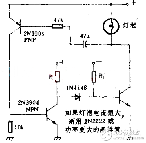
Inrush current is the main cause of lamp failure. This circuit can limit this current; however, it provides normal current to the filament when it reaches its normal operating temperature. This circuit is also suitable for low voltage pilot lights. However, any type of bulb can be used as long as the voltage and current do not exceed the rated parameters of the transistors used.
ZGAR electronic cigarette uses high-tech R&D, food grade disposable pod device and high-quality raw material. All package designs are Original IP. Our designer team is from Hong Kong. We have very high requirements for product quality, flavors taste and packaging design. The E-liquid is imported, materials are food grade, and assembly plant is medical-grade dust-free workshops.
Our products include disposable e-cigarettes, rechargeable e-cigarettes, rechargreable disposable vape pen, and various of flavors of cigarette cartridges. From 600puffs to 5000puffs, ZGAR bar Disposable offer high-tech R&D, E-cigarette improves battery capacity, We offer various of flavors and support customization. And printing designs can be customized. We have our own professional team and competitive quotations for any OEM or ODM works.
We supply OEM rechargeable disposable vape pen,OEM disposable electronic cigarette,ODM disposable vape pen,ODM disposable electronic cigarette,OEM/ODM vape pen e-cigarette,OEM/ODM atomizer device.

Disposable Vape, bar 3000puffs, ZGAR bar disposable, Disposable E-cigarette, OEM/ODM disposable vape pen atomizer Device E-cig, ZGAR 25 Vape
ZGAR INTERNATIONAL(HK)CO., LIMITED , https://www.zgarpods.com