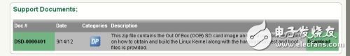
Bare-metal control peripherals are very simple, and they are no different from ordinary single-chip microcomputers, but only the streaking code is far from playing the role of Cortex-A9 hard core. After all, Zynq chip integrates a dual core that can run up to 1GHz. CPU (XC7Z020 on ZedBoard can only reach 800MHz). And the ZedBoard is equipped with Gigabit Ethernet, HDMI and USB OTG interfaces, and it is not wasted without running the operating system. Some friends want to do WinCE on ZedBoard, but this information is extremely scarce, and WinCE is a large operating system with high copyright cost, so open source has small embedded Linux has become the first choice. In order to make a graphical interface, the rabbit was also committed to porting the desktop Linaro Ubuntu system. However, the reference examples given by ADI have not been optimized, and the official version of Xillinux has been delayed and only supports simple VGA with low color. The interface (the VGA on the ZedBoard doesn't even have a 16-bit color), so the rabbit had to give up the previous work and re-enable the ZedBoard factory default lightweight Linux. This system does not have a graphical desktop, but it already includes a network card, HDMI driver and other basic functions, enough to use. The most important part of controlling peripherals under Linux is the driver, but before you start the handwriting driver, you need to do some preparatory work. In order to reduce the workload, we directly modify the ZedBoard factory demo, join the previously completed my_gpio peripherals, and implement the Bootloader function through U-Boot. The source project for this demo can be found on the ZedBoard page of Digilent's website: NavPath=2,400,1028&Prod=ZEDBOARD Click on Download below to download the ZedBoard_OOB_Design.zip file, which contains XPS projects, U-Boot files, Linux. Kernel configuration files, DeviceTree source files, rootfs, etc. There are similar operating instructions in README.txt, it is recommended to read it again.
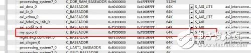
The default XPS system project on ZedBoard is located in the hw\xps_proj folder. Double-click system.xmp to open the project. Import the my_gpio peripheral IP core into the project as described above. Portal: ZedBoard Learning Notes (2) Developing a custom AXI bus peripheral IP core - After taking LEDs and switches as an example, check if XPS allocates address space for our peripherals. If not, you need to manually set one. Address, here we set to 0x75C80000, the space size is 64K unified AXI equipment.
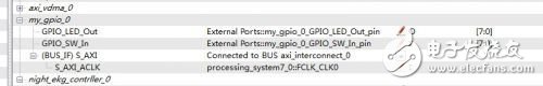
Set up the bus connection according to the method in ZedBoard Learning Notes (2). The result is as follows:
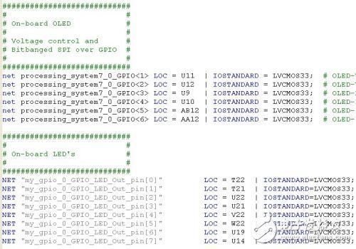
Modify the xps_proj\data\system.ucf file to assign external pins to the my_gpio peripheral (the pin names in the ucf constraint file must be the same as those in Ports, and many users have had problems here).
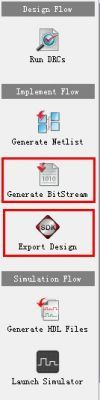
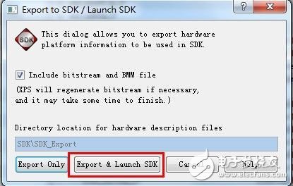
After completing, click Generate BitStream to generate configuration data, then click Export Design, and select Export & Launch SDK to export the hardware information to the SDK.
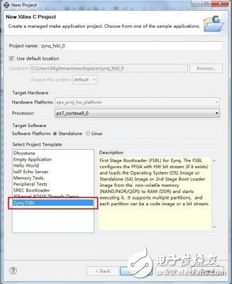
In the SDK, create a new C project, different from the bare machine HelloWorld, this time to build a bootloader, so select the FSBL project, that is, First Stage Bootloader, to achieve initialization and startup work before U-Boot. Other options are available by default.
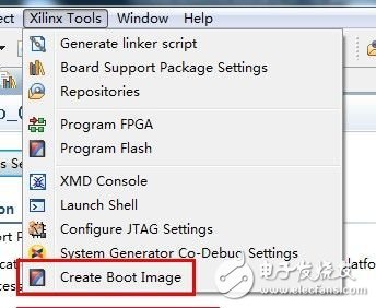
Compile the project. After the completion, the SDK will generate the FSBL elf file. In addition, the System.bit exported from XPS and the u-boot.elf compiled in the first article can be used to implement the SD card. Start the system's full bootloader file. U-boot.elf is included in ZedBoard_OOB_Design, but this rabbit has not tried, the method of compiling u-boot.elf by Xilinx U-Boot can be found in: ZedBoard Learning Notes (1) First Step - Establishing Xilinx Cross Compilation Environment Set After these three files are combined, click on Xilinx Tools→Create Boot Image, add to the list, select an output path, and you can create a bootloader.
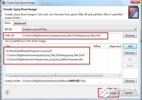
The SDK will generate the u-boot.bin file in the output path, change it to BOOT.bin, copy it to the SD card, and configure the appropriate jumper for the ZedBoard board. Then open the ZedBoard power supply, the Bootloader will initialize the PS, configure the PL with BitStream (including the my_gpio peripheral we created), and hand over the operation rights to U-Boot. U-Boot will automatically load Device Tree, Linux kernel image and RootFS, and finally start Linux. ZedBoard also comes with zImage, devicetree and rootfs files in the SD. These files can be used in the original. The C language driver compiled directly with the Xilinx cross-compiler can run and control the peripherals on this system. Of course, if you want to compile the kernel yourself, or do not want to call the peripherals with a static physical address, you need to go one step further. Note that this step is not necessary for controlling AXI bus custom peripherals under Linux. In order to make a further study for interested friends, the rabbit here will talk about compiling the Linux kernel and device tree running on ZedBoard. Of course, this method is also recorded in detail in the README file of ZedBoard_OOB_Design. In the Linux environment of the PC (the rabbit here is Ubuntu), download the Digilent Linux kernel source code via Git command: git clone git://github.com/Digilent/linux-3.3-digilent.git Switch to ZedBoard Branch: cd linux-3.3- Digirentgit checkout -b zedboard_oob v3.3.0-digilent-12.07-zed-beta Copy the .config file from ZedBoard_OOB_Design to the source directory and compile the kernel (refer to the directory where ZedBoard_OOB_Design is located): cp /linux/.config ./. The kernel image zImage generated by configmake is located in the /arch/arm/boot/ folder. Then modify the devicetree_ramdisk.dts file to add my_gpio peripheral information. /******* LED & SwTIch Controller ******/my_gpio@75c80000 { compaTIble = "xlnx,my_gpio-1.00.a"; reg = <0x75c80000 0x10000>; xlnx,dphase-TImeout = <0x8 >; xlnx,family = "virtex6"; xlnx,c_num_reg = <0x1>; xlnx,c_num_mem = <0x1>; xlnx,s-axi-min-size = <0x1ff>; xlnx,c_slv_awidth = <0x20>; xlnx, C_slv_dwidth = <0x20>; xlnx,use-wstrb = <0x0>;}; Generate the device tree with the following command, also copy to the SD card: ./scripts/dtc/dtc -O dtb –I dts –o ./devicetree_ramdisk .dtb \ /linux/devicetree_ramdisk.dts This device tree file is used by netizens to add drivers to the kernel, but the rabbit thinks it is not. If you do not want to load the driver through the static device physical address (0x75c80000 above), you can dynamically identify the device based on this device tree information (specifically via xlnx, my_gpio-1.00.a string). The specific method of interest for children's shoes can be tried, next time we will start to officially write the Linux driver for my_gpio peripherals.
DC Multi-channels Power Meter
DC meter for solar power multi-channel monitoring. This is a multi-channel power measuring system with LCD display and Modbus RTU communication, available 9 DC channels or 21 channels with an external module provides current, voltage, frequency and bi-directional energy electricity parameters. It`s a perfect measuring component for the renewable power generation industry such as wind power, PV solar power etc.
Dc Multi-Channels Power Meter,Ev Charger Digital Power Meter,Ev Charger Dc Power Meter Multifunctional,Multi-Channel Power Meter For Solar
Jiangsu Sfere Electric Co., Ltd , https://www.elecnova-global.com